M20_Ope_E - 第202页
Chapter 5 Libraries 5-52 Note: The brightness threshold is set based on “BRI GHT” result displayed when image test is performed. Note: The component orientation check is not available for BGA, connector and BGA/CSP compo…
Chapter 5 Libraries
5-51
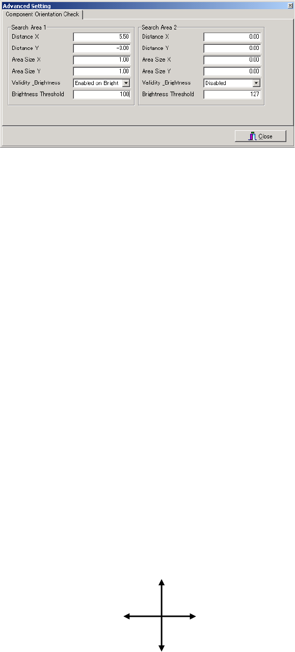
Component Orientation Check Setting Window
Window:
Search Area 1 / 2 Up to two sets of feature search conditions can be set. If two sets are set,
the orientation check result will be OK only when both results are OK.
(If one or both fails, the orientation check result will be NG.)
Distance X X-directional distance from the center of the component to the center of
lead (feature section)
Distance Y Y-directional distance from the center of the component to the center of
lead (feature section)
Area Size X Size of search area (X direction) for the feature section
Area Size Y Size of search area (Y direction) for the feature section
Validity _Brightness
Select one of the following three brightness conditions.
Disabled : The component orientation check function is disabled (not used).
Enable on Bright : The orientation check result is OK if the average brightness inside
the search area is higher than the brightness threshold.
Enable on Dark : The orientation check result is OK if the average brightness inside
the search area is lower than the brightness threshold.
Brightness Threshold
The average brightness inside the search area after image test iscompleted
is measured, and then approximately half of the measured brightness is
entered as the brightness threshold.
Note: When setting distances X and Y, the distance (mm) from the component’s center to the feature
section and its direction (±) must be taken into account. The X and Y directions (coordinate
system) used for component orientation check are shown below. This differs from the PCB’s
coordinate system, so care must be taken when setting the direction (±) of the distances X and
Y.
Note: The component orientation check is performed only when normal position detection image
processing is completed successfully. This means that the search areas are determined with the
correction result of the component position (X, Y, angle) taken into account. As a result, relative
position between component’s center and search area will never be deviated even if the
component pickup position shifts.
Y(-)
X(+)
X(-)
Y(+)
Chapter 5 Libraries
5-52
Note: The brightness threshold is set based on “BRIGHT” result displayed when image test is
performed.
Note: The component orientation check is not available for BGA, connector and BGA/CSP
components.
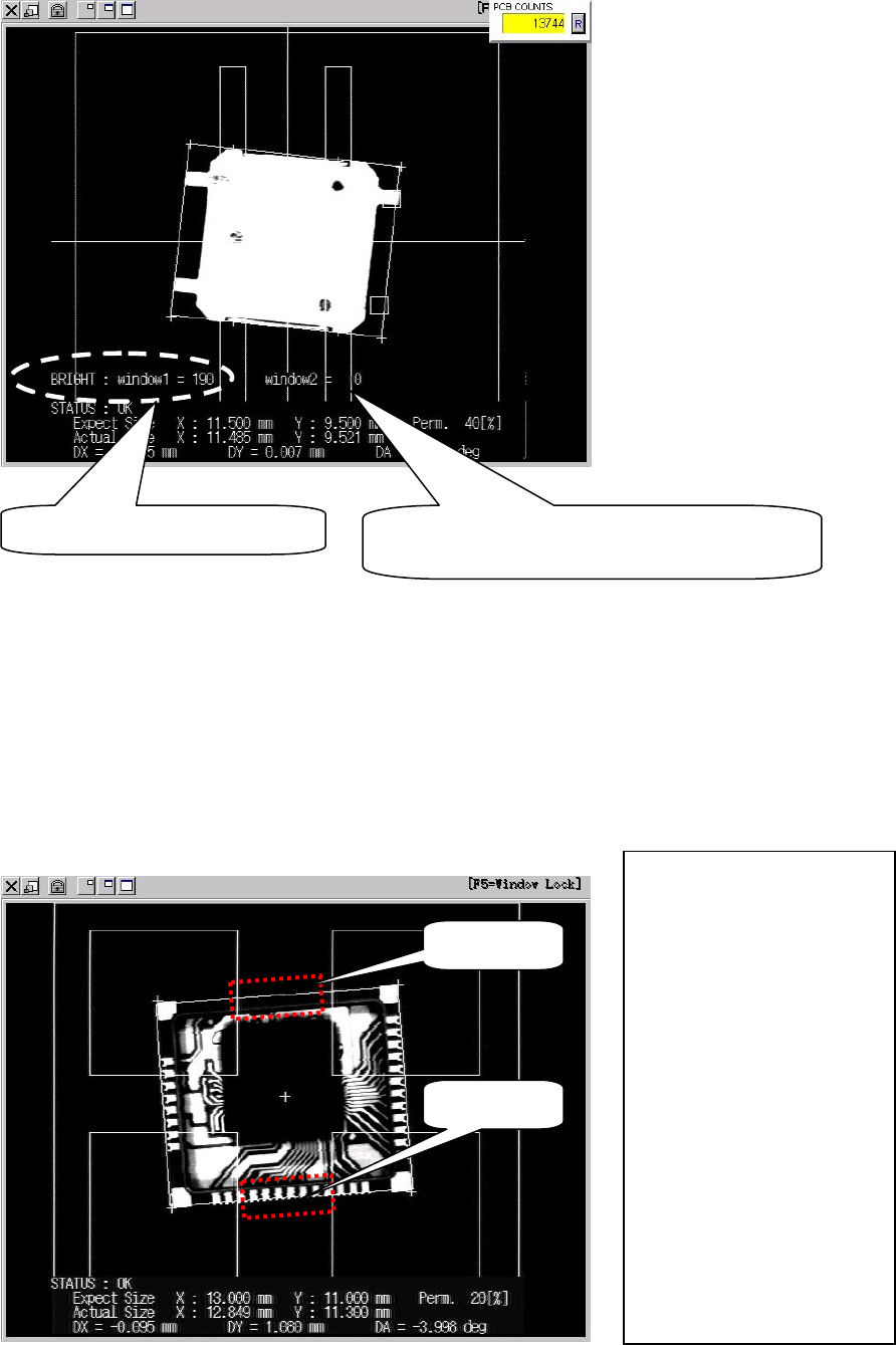
●Orientation check setting example
If “Enabled on Bright” is set for one search area and “Enabled on Dark” for the other (when
two search areas are used), component orientation check can be performed with higher
accuracy, since the two brightness thresholds will not be satisfied if the component is picked up
in an excessively wrong orientation. The following is an example in which both “Enabled on
Bright” and “Enabled on Dark” are set.
Average brightness in search area
If two search areas are used, the average
brightness of search area 2 will be displayed.
Search area 2
Search area 1
Component size X: 13.00mm
Component size Y: 11.00mm
Search area 1
Distance X: 0.00mm
Distance Y: -5.50mm
Area size X: 5.00mm
Area size Y: 2.00mm
Validity _Brightness:
“Enabled on Dark”
Brightness threshold: 100
Search area 2
Distance X: 0.00mm
Distance Y: 5.50mm
Area size X: 5.00mm
Area size Y: 2.00mm
Validity _Brightness:
“Enabled on Bright”
Brightness threshold: 100
Chapter 5 Libraries
5-53
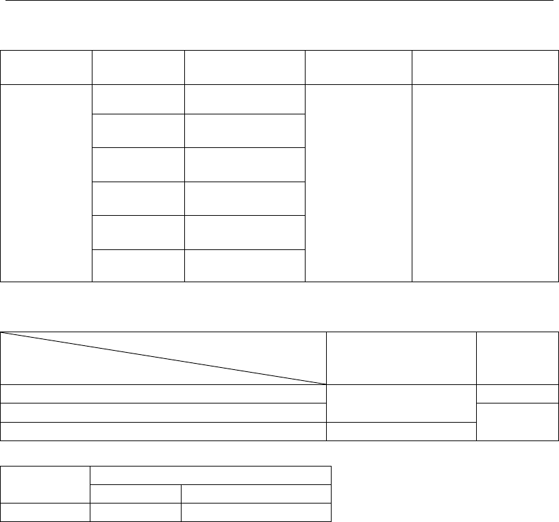
5-1-5-4 Camera Assignment
Refer to the camera specs. shown below for assigning an appropriate camera for the
component (use for image test and ADA).
Camera type
Vision
process
Applicable max.
component size
Applicable min.
lead pitch
Applicable min. ball
diameter/ball pitch
Multi-Scan
Camera
Whole View 0402 to 40 mm sq.
0.3 mm
Ball damage check
disabled.
Ball diameter: 0.2 mm
Ball pitch: 0.4 mm
Ball damage check
enabled.
Ball diameter: 0.4 mm
Ball pitch: 0.65 mm
2 Views
Horizontal
80 x 40 mm
2 Views
Vertical
40 x 80 mm
3 Views
Horizontal
120 x 40 mm
3 Views
Vertical
40 x 120 mm
4 Views 80 mm sq.
Relationship between applicable maximum component size and component height
Component height + PCB thickness +
pre-mounted component height
Component height
0 to 28 mm 28 to 55 mm
0 to 15 mm
80 mm sq./120 x 40 mm
(40 x 120 mm)
36.7 mm sq.
15 to 17 mm
25.4 mm sq.
17 to 25 mm 25.4 mm sq.
Camera type
Mark size
Fiducial mark
Bad mark
Teach camera
0.2 to 5 mm Mark color: White/black