M20_Ope_E - 第208页
Chapter 5 Libraries 5-58 (Cente r-molded lead ro w) One-si de lead ed (Center-l eadl es s l ead row) (Center-molded lead rows ) (Cener-leadless lead rows) Two-side lead ed Placement Point (the center of the inspected l…

Chapter 5 Libraries
5-57
5-1-5-9 Blob Process
Blob Horizontal / Blob Vertical
White blobs with sizes more than "Blob X" and "Blob Y" are recognized as electrodes. In view of
allowance, enter 1/4 to 1/2 electrode size for "Blob X" and "Blob Y". Noises which come under
the size can be neglected.
Blob Area
Larger than the white blobs entered in “Blob area” are recognized as electrodes.
If you do not etner the blob area, approx. one-eighth area calculated from Overall XY and will
be automatically entered in “Blob area”.
Result of Image Processing (Display of the monitor screen)
Blob size: White blob dimensions are recognized as electrodes.
Detected areas are displayed in descending order as; [0], [1], [2]….
Area: The area white blobs are recognized as electrodes. (Unit: 0.01mm
2
)
Expert Sqr Size: Diagonal length of the rectangle defined by outer XY sides of white
blobs entered in Image Library edit window.
Actual Size : Actual measurement diagonal length of the rectangle defined by
outer XY sides of white blobs.
5-1-5-10 CPL Process
1
Normally, specify zero at “Prov.Position.” You can change the size and position of the
provisional positioning window.
Normally, specify zero at “Min Detect Size.” When a value is set to “Min Detect Size,” the
system recognizes an image having the Min Detect Size or longer length and ignores an image
having shorter length than the Min Detect Size.
5-1-5-11 Connectors
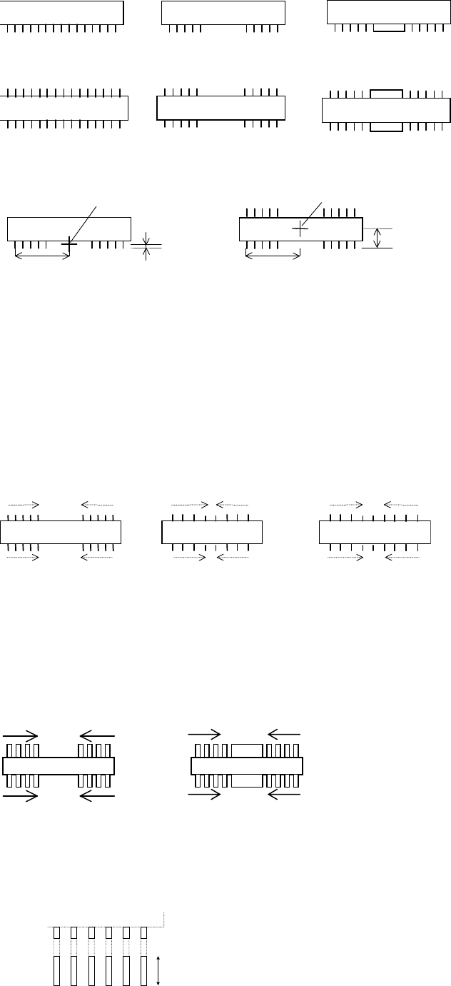
Applicable Component Styles
One-side leaded connector: With two or more leads. Only the leads reflect light. Center-leadless
lead row or center-molded lead row (see the below figure) can also be handled.
Two-side leaded connector: With two or more leads per side (4 or more in total). Only the leads
reflect light. Center-leadless lead rows or center-molded lead rows can also be handled
provided the opposing lead rows are symmetrical; if not symmetrical, the connector must be
handled with the one-side leaded mode.
Note: A Component with leads staggered both sides is applicable.
1
CPL: Coarse Part Location (Provisional Positioning)
Chapter 5 Libraries
5-58
(Center-molded lead row)One-side leaded (Center-leadless lead row)
(Center-molded lead rows)
(Cener-leadless lead rows)
Two-side leaded
Placement Point (the center of the inspected lead rows)
Placement point
Lead Row / 2
Placement point
Lead Foot / 2
Lead Row / 2
Overall Y / 2
Settings
Only settings that require notice are described in this section.
z Handle Lead
Lead count from either end to the center to inspect for lead bending. This does not mean the
present lead count.
5 leads 5 leads
5 leads5 leads
4 leads 4 leads 4 leads 4 leads
4 leads4 leads4 leads4 leads
Handle Lead = 4Handle Lead = 4Handle Lead = 5
Normally, specify zero at "Handle Lead". At this setting, the number of leads is not counted,
but, "Lead Pitch" and "Lead Row" are checked, which is equivalent to counting leads. When
some center leads are lacking, or there is a large electrode in the middle, all the leads are not
equally spaced, and specify the number of handled leads, counting from the end, at "Handle
Lead". Never set the number of all the leads at "Handle Leads".
Example: In the below figure, type 4 at "Handle Lead".
4 leads 4 leads
z Lead Foot
If the video image of the leads looks like the below figure, enter the length indicated by the
arrow:
Chapter 5 Libraries
5-59
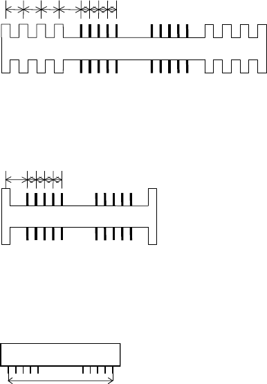
z Skip Lead Count
Some connectors have mold stick-outs at the outer sides of the lead row, which may be
mis-identified by the vision system as leads. To prevent this, specify how many wrong-pitched
stick-outs to be skipped. If the interval between such stick-outs equals the lead pitch, they are
not skipped.
Example: Skip Lead Count = 4
Four wrong-pitched stick-outs are skipped.
Example: Skip Lead Count = 4
When there is only one wrong-pitched stick-out, only this one is ignored.
z End Lead Pitch
The distance between the outermost leads.
How to calculate the Lead Row setting:
(Lead count/side - 1) x LeadPitch = End Lead Pitch
For a missing-leaded component, assume the leads are not missing in this calculation.
When the difference between this setting and the actual measurement is;
± {LeadBendPerm + (LeadPitch/3)} or less, the component will be accepted.