M20_Ope_E - 第211页
Chapter 5 Libraries 5-61 * When [Prov. Position]=0 The following shows how the size and position of the provisional positioning windows are determined by the component dimensions. This algorithm applies to all the connec…
Chapter 5 Libraries
5-60
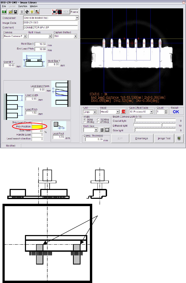
z Prov. Position
When the component is picked up at its off-centered position, the component position when
presented to the camera for image acquisition is off-centered accordingly. When the amount of
the off-centering exceeds an acceptable range, provisional positioning error will result. For the
component to be vision-processed at a desired position, [Prov. Position] setting needs to be
modified.
Example: To pick up a component at an off-centered point as shown below, set [Prov. Position] to “15”.
Provisional positioning windows
The right and left position of the
component video image shot by
the upward-looking camera is
reversed.
Chapter 5 Libraries
5-61
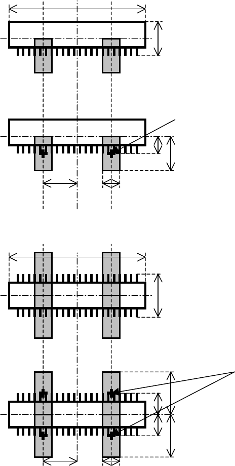
* When [Prov. Position]=0
The following shows how the size and position of the provisional positioning windows are
determined by the component dimensions. This algorithm applies to all the connector modes
(one-side leaded mode and two-side leaded mode).
Overall X
Overall Y
Prov. Position = 0
Center of the window
Overall Y
Overall Y / 2
Overall X / 4 Lead Pitch
3
Overall X
Overall Y
Prov. Position = 0
Center of the window
Overall Y
Overall Y / 2
Overall X / 4 Lead Pitch
3
Overall Y / 2
Overall Y
Chapter 5 Libraries
5-62
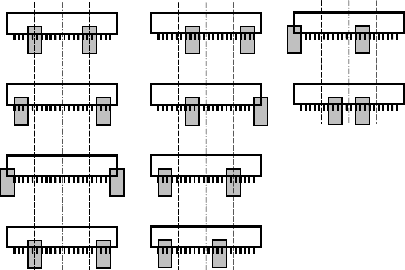
* Moving the provisional positioning windows
By modifying the first digit of [Prov. Position], you can change the position of the provisional
positioning windows.
Followings are available for [CPL] or [Connector] processings:
Prov. Position = ?0
Prov. Position = ?5
Prov. Position = ?1
Prov. Position = ?6
Prov. Position = ?2
Prov. Position = ?7
Prov. Position = ?3
Prov. Position = ?4
Prov. Position = ?8
Prov. Position = ?9