M20_Ope_E - 第219页
Chapter 5 Libraries 5-69 z Component Click <Mode> button to select a ball alignment pattern. 0: Full grid, matrix 1: Full grid, staggered 2: Perimeter grid, matrix 3: Perimeter grid, staggered 4: Partial grid, matr…

Chapter 5 Libraries
5-68
5-1-5-12 BGAs and CSPs
Inapplicable Components
Components with mold that reflects light, such as CBGA361T1.27-DC71, CBGA240T1.27-ISO,
CCGA625T1.27-ISO, and TBGA240T1.27-DC56, cannot be vision-processed properly.
Some CSPs use polyimide tape as their packaging material. Note that the polyimide tape is
easily delaminated to rise above the ball bumps, resulting in mis-imaging of the component.
Editing Placement Coordinates for BGAs and CSPs
Usually placement coordinates editied with teach entry may include some offsets, since the
operator manually aligns the camera center (cross hairs on the CRT monitor) to the placement
point. For components such as a chip, QFP, and SOP, whether their placement coordinates are
accurate can be checked by checking the placed components. But for a BGA or CSP, such visual
checking is not feasible. Unless the placement coordinates of a BGA or CSP are accurate,
satisfactory placement cannot be performed. Therefore we strongly recommend to use CAD
data as placement data for BGAs and CSPs.
When teaching placement coordinates of a BGA or CSP via the main teach camera, the
maximum allowable coordinate offset is one-third of the ball diameter.
Ball check
For BGA and BGA/CSP components, the ball check method can be selected from
“Presence(outmost)”, “Presence(all)”, “Presence&Damage(all)” and “No Checks”. However,
“Presence&Damage(all)” cannot be selected in the case of scan camera.
Note: If “No Checks” is selected, ball positioning will be performed, starting with the ball that is
located, among those located inside the four-edged search area, at the most outside position.
Unlike “Presence(outmost)”, this method may judge that a ball is located on the circumference
even if it is not. In this case, deviation in position or angle may occur, so “No Checks” must be
selected only for special components that cannot be positioned by any other methods.
Note: The system can recognize missing balls that are lost during manufacturing. When the ball does
not appear white (not reflect the front lighting), the system recognizes ball absence.
Note: When a ball is flattened to a considerable extent, the system can detect it. However, this ability
is crucially affected by the illuminator settings including the side light’s.
Settings for BGA and BGA/CSP are respectively described in the following sections.
Settings for BGA mode (ImageLibrary>SelectComponent>BGA)
BGAs can be handled either via the BGA mode or the BGA/CSP mode. But we
recommend you to use the BGA/CSP mode for handling BGAs.
As for Ball Pitch, Ball Size, Ball Count X, Ball Count Y, Upper-right Ball Coordinate, Lower-left
Ball Coordinate, click on each setting field and see the graphical description displayed in the
sub-windows.
Chapter 5 Libraries
5-69
z Component
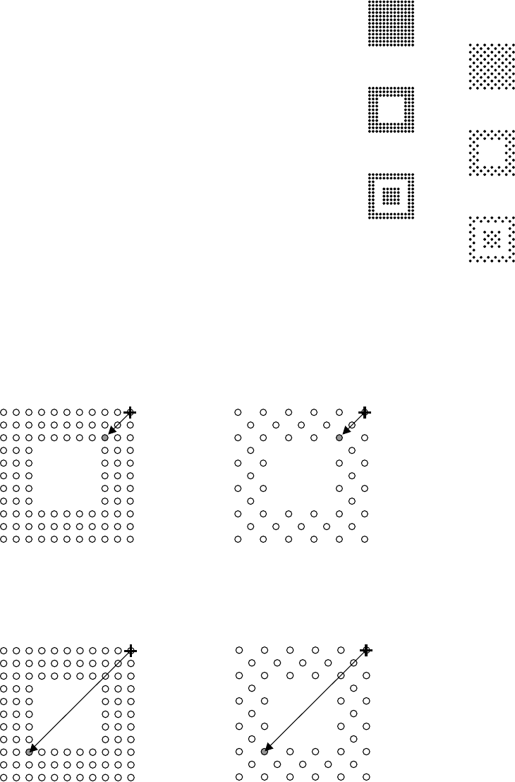
Click <Mode> button to select a ball alignment pattern.
0: Full grid, matrix
1: Full grid, staggered
2: Perimeter grid, matrix
3: Perimeter grid, staggered
4: Partial grid, matrix
5: Partial grid, staggered
z Upper-right Ball Coordinate (When [Component] is 2 or 3)
Note: For information on how to identify the ball position, see Missing Ball Assignment later in this
section.
Enter the ball position number of the upper right corner of the innermost ball square. For both
examples shown below, the setting shall be “0303”.
z Lower-left Ball Coordinate (When [Component] is 2 or 3)
Enter the ball position number of the lower left corner of the innermost ball square. For both
examples shown below, the setting shall be “0909”.
0
2
4
1
3
5
Chapter 5 Libraries
5-70
z Ball Pitch Perm.
An error occurs when the measured ball pitch is out of the range of,
Specified ball pitch +/- Ball pitch permission.
Larger the value, less severe the requirement will be.
When
Measured ball pitch < Specified ball pitch - Ball pitch permission,
or
Measured ball pitch > Specified ball pitch + Ball pitch permission,
an error occurs.
Unit:mm, Standard: 0.2
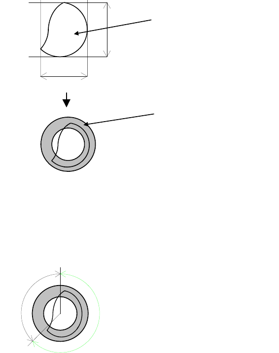
z Ball Circum. Perm.
Check is made on how much the ball circumference measured in the process of [Ball Check]
>Presence&Damage is in the circumference permission range determined from actually
measured ball size. Larger the value, less severe the requirement will be.
Unit: %, Standard: 40
Circumference
Actual measured ball size=(A+B)/2
Circumference permission range
This permission is determined in percent. Even if the ball is proper, the circumference may be
slightly out of the range.
Example: Improper ball:
The circumference is about 45% out of the range. When the setting is 40, the error mark is
displayed.
OK
NG
Circumference permission = NG/(OK+NG)
Note: This function is only available when “Still” is selected in [F.Camera On-The-Fly Capture].