M20_Ope_E - 第23页
Chapter 1 General 1-5 Rear View Note: Configuration of the control switches varies depending on each machine configuration. 3. READY 5. START 4. RESET 6. STOP 8. ACTIVE 7. CLEAR 9. DOCKING 2. Emergency Stop switch P O T …
Chapter 1 General
1-4
M20
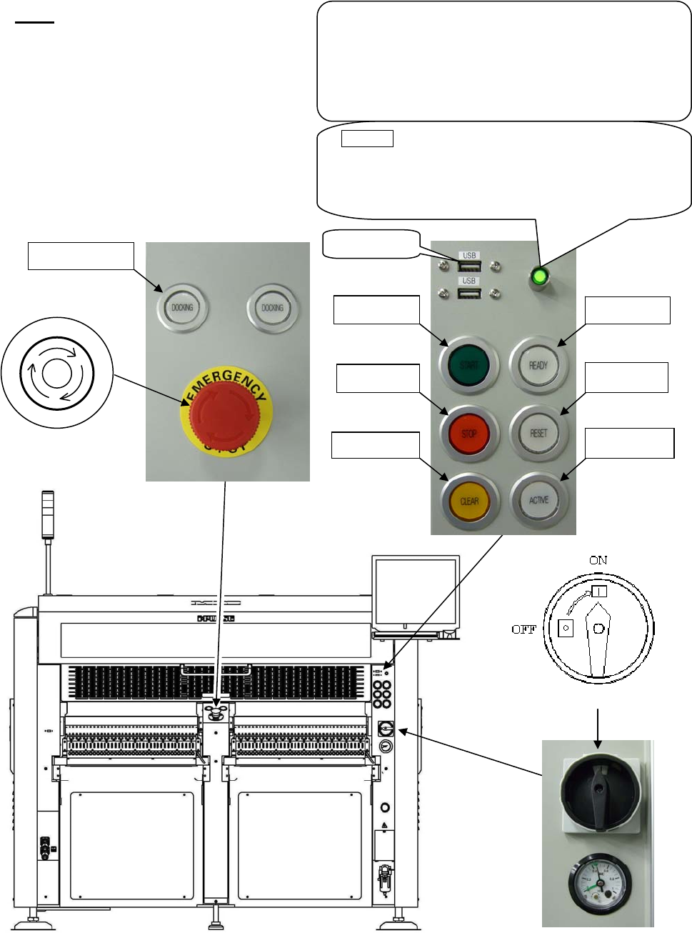
Front View
Note: Configuration of the control switches varies depending on each machine configuration.
3. READY
5. START
4. RESET
6. STOP
8. ACTIVE
7. CLEAR
USB
p
ort
POWER (Green lamp)
This lamp lights up green when the machine computer
is turned on. Normally this button is not used. Use it
only when the machine computer does not start up
even if the main switch button is pressed.
UPS option
The UPS backs up the power supply of the machine
computer, LCD, and servo motors for controller when
electric failure occurs but does not backs up the power
supply of servo motors for driving.
To shut down the UPS, hold down this button over five
seconds.
9. DOCKING
2. Emergency Stop switch
P
O
T
S
E
Y
C
N
E
G
R
E
M
1. Main Switch
Chapter 1 General
1-5
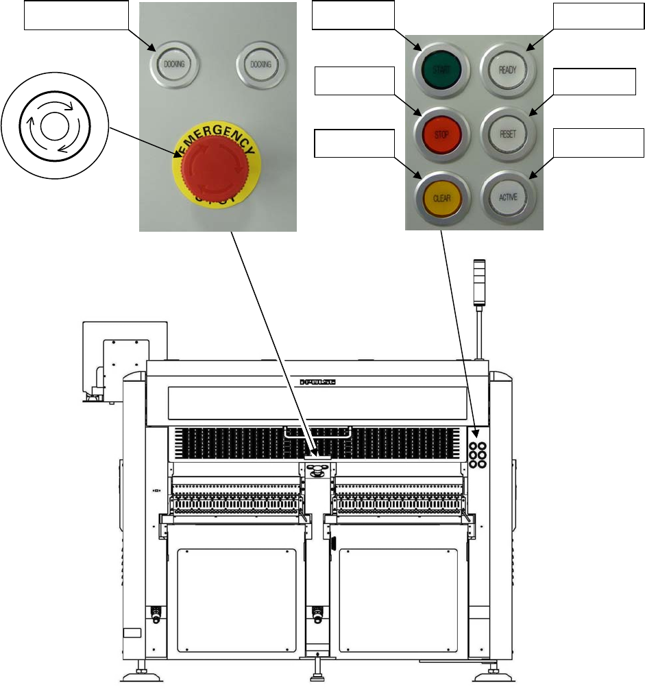
Rear View
Note: Configuration of the control switches varies depending on each machine configuration.
3. READY
5. START
4. RESET
6. STOP
8. ACTIVE
7. CLEAR
9. DOCKING
2. Emergency Stop switch
P
O
T
S
E
Y
C
N
E
G
R
E
M

Chapter 1 General
1-6
1-1-1-1 Operation Switches
1. MAIN
switch
Turns on and off the mounter. Turn the switch clockwise to turn on the mounter. Turn the switch
counterclockwise to turn off the mounter.
2. EMERGENCY STOP
(EMG) switch
Press this switch for an immediate stop of the mounter in an emergency. The motors that drive the
machine heads stop at once with a continuous beep.
This switch locks when it is pressed. Release it by rotating it clockwise. There are two
EMERGENCY STOP
switches, one is on the front panel and the other is on the rear panel.
3. READY
switch
Turns on the servo motors that drive the mounter heads. For safety reasons, the servo motors are
automatically turned off when the EMERGENCY STOP
is pressed. Also, they can be turned off from
the Maintenance menu.
Pressing this button unlocks the covers. At the same time, the servo motors are turned off for safety.
Pressing this button again locks the covers and turns on the servo motors automatically.
4. RESET
switch
Stops running. First press the STOP
switch to pause running and then press the RESET switch
to stop running.
5. START
switch
Starts running (job run/test run).
6. STOP
switch
Stops running temporarily. When this switch is pressed, the mounter stops after the completion of
the current cycle (a placement step). Press the START
switch to resume, or the RESET switch to
end the job.
7. CLEAR
switch
Press this switch once to clear alarm sound in component lack or at an error occurrence, etc. Press
this switch again to recover from the error while the switch blinks.
8. ACTIVE
switch
Activates the control switches on the front or rear side which the switch is pressed. And the pressed
ACTIVE
switch lights up.
9. DOCKING
switch
Clamps and unclamps the CFB-36 (changeable feeder bank) or the CTF-40 (changeable tray feeder).
10. SETUP
switch
Locks and unlocks the cover of the tray feeder. And resets the remaining number of tray
components.
Note: Both the front and rear EMERGENCY STOP
switches are always enabled irrespective of which the
ACTIVE
switch is enabled.
Note: Configuration of the control switches varies depending on each mounter options.
Note: There are three types of feeder banks.
FFB ········· Fixed feeder bank
CFB-36 ····· Changeable feeder bank (Option)
CTF-40 ····· Changeable tray feeder (Option)