M20_Ope_E - 第236页
Chapter 5 Libraries 5-86 5-1-5-14 Bad Marks Bad Mark Process Logic Mark On Mark Off Positive Skip Place Negative Place Skip Mark Color For easy recognition, mark the bad mark in silver or white for glass epoxy boards…
Chapter 5 Libraries
5-85
Action: Center searching based on a fiducial shape:
The shape should be circle, square, triangle or corner square. (Maximum size : □3.0mm)
① In the Fiducial Data dialog box, select [Center Search] for [Algorithm].
② Enter all the required data.
③ When the coordinates of the fiducial center are not yet entered, click
Prearrange>Teach&Move Pallet to perform teach entry. When the coordinates have been
entered, use the Trace menu to move the main teach camera to the coordinates.
④ Adjust the Gain, Offset, and Inside/Outside Light settings so the fiducial image is shot
clearly.
⑤ Click <Image Test> button to execute image test. Confirm the test ends in success.
⑥ Save the data.
Pattern matching:
There is no restriction in shape, however circle is ideal. The size isφ0.2mm to φ1.0mm.
This method is most suitable for the mark plated with silver, gold or nickel etc.
① In the Fiducial Data dialog box, select [Pattern Matching] for [Algorithm].
② Enter all the required data.
③ When the coordinates of the fiducial center are not yet entered, click
Prearrange>Teach&Move Pallet to perform teach entry. When the coordinates have been
entered, use the Trace menu to move the main teach camera to the coordinates.
④ Adjust the Gain, Offset, and Inside/Outside Light settings so the fiducial image is shot
clearly.
⑤ Click <Model Centering> button to center the fiducial.
⑥ Click <Acquire Model> button to acquire the model.
⑦ Click <Image Test> button to execute image test. Confirm the test ends in success.
⑧ Save the data.
Chapter 5 Libraries
5-86
5-1-5-14 Bad Marks
Bad Mark Process
Logic Mark On Mark Off
Positive Skip Place
Negative Place Skip
Mark Color
For easy recognition, mark the bad mark in silver or white for glass epoxy boards, and mark in
black for ceramic boards.
There is no restriction in shape. The size would be φ2.0mm to φ5.0mm.
The mark color should be in contrast with the surrounding board.
Board Mark color
Glass epoxy (dark green) White or silver
Ceramic (white or pale green) Black
Creating Bad Mark Data
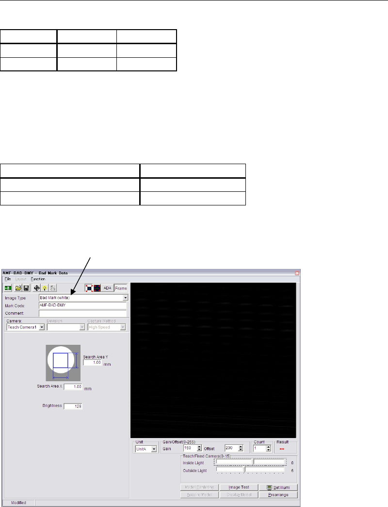
Window:
File>Open: Opens the list of existing bad mark data. Select data and click
<Open> button. To delete data, select data and click <Delete>
button.
File>Save As…: Saves the current file with a name and comment. Comment is not
necessarily required.
File>Save: Overwrites the current file.
File>Exit: Closes the Bad Mark Data dialog box.
Image Type: Click <Mode> button to switch [Bad Mark (white)] and [Bad Mark
(black)].
Mark Code: To create new data, enter a desired code. To edit existing data, click
<Open> button to select data.
* Up to 38 characters can be entered.
Mode selecting combo box
Chapter 5 Libraries
5-87
Comment: Any appropriate comment.
* Up to 40 characters can be entered.
Brightness: Threshold value to see white or black of the inspection point;
Higher score than this represents white, lower black. (standard :
127)
Search Area X: Length of the inspection area in the X (horizontal) direction.
Usually enter 1 to 2mm.
* Increment : 0.01mm
Search Area Y: Length of the inspection area in the Y (vertical) direction.
Usually enter 1 to 2mm.
* Increment : 0.01mm
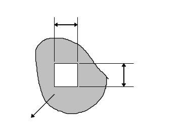
S
earch area X
Search area Y
Bad mark
Note: Define smaller search area than the bad mark size; The mark location may vary from board to
board.
Action:
① In the Bad Mark Data dialog box, select the bad mark color (white/black) for [Image
Type] by clicking <Mode> button.
② Enter all the required data.
③ Click Prearrange>Teach&Move Pallet to teach the coordinates of the bad mark center.
④ Adjust the Gain, Offset, and Inside/Outside Light setting so the bad mark image is shot
clearly.
⑤ Click <Image Test> button to execute image test. Confirm the test ends in success.
⑥ The bad mark should ideally score Measure=255 for white color, and Measure=0 for black
color in the image test. Re-adjust the illuminator setting and redo the image test until the
score approaches 255/0 as possible.
⑦ Move the main teach camera to capture the resist part around the bad mark. Adjust the
Inside/Outside Light setting and execute image test until Measure=0(for white color)/
Measure=255(for black color) can be obtained.
Note: If Measure=255 and 0 cannot be obtained even the illuminator setting is properly adjusted, add
the Measure value for the bad mark and the resist part, divide the value by 2, and enter the
value to [Brightness] of the Bad Mark Data dialog box.
⑧ Save the data.
For white bad marks, when the brightness in the specified search area at "Search Area Y" and
"Search Area X" is more than "Brightness", OK is issued.
For black bad marks, when the brightness in the specified search area at "Search Area Y" and
"Search Area X" is less than "Brightness", OK is issued.