M20_Ope_E - 第245页
Chapter 5 Libraries 5-95 5-2-3 Tray Library (Tray Data) Menu: Program>TrayData Program>PickuData>Package/Tray>TrayData Register tray data for use of th e tr ay feeder. Before creating the tray librar y data, …
Chapter 5 Libraries
5-94
Note: When using JEDEC pallets, the front/rear positioning block offset values are X=0/Y=170. To
obtain accurate offset values, teaching must be performed.
Link to the library can be made for the same tray only.
Note: MX-ST2 and MX-20 share the same concept of reference point, except that they differ in their
structure. When using JEDEC pallets, the front/rear positioning block offset values are
X=0/Y=180. To obtain accurate offset values, teaching must be performed.
Note: MX-RT1 and MX-20 share the same concept of reference point, except that they differ in their
structure. When using JEDEC pallets, the front/rear tray offset value is approximately Y=140.
To obtain accurate offset value, teaching must be performed.
Chapter 5 Libraries
5-95
5-2-3 Tray Library (Tray Data)
Menu: Program>TrayData
Program>PickuData>Package/Tray>TrayData
Register tray data for use of the tray feeder. Before creating the tray library data, the pallet
library data must be created.
Window:
File>Save: Saves the edited data.
Tray: Tray name. Serves to relate the tray library and the pickup data
editor (program editor).
* Up to 500 records can be registered.
*
Up to 14 characters can be entered.
Pitch X: Component pitch in the X direction.
* Unit : 0.01mm
Pitch Y: Component pitch in the Y direction.
* Unit : 0.01mm
Count X: Number of component columns (X direction).
* The number can be entered up to 999.
Count Y: Number of component rows (Y direction).
* The number can be entered up to 999.
Original X: X coordinate of the original pickup point
* Unit : 0.01mm
Original Y: Y coordinate of the original pickup point
* Unit : 0.01mm
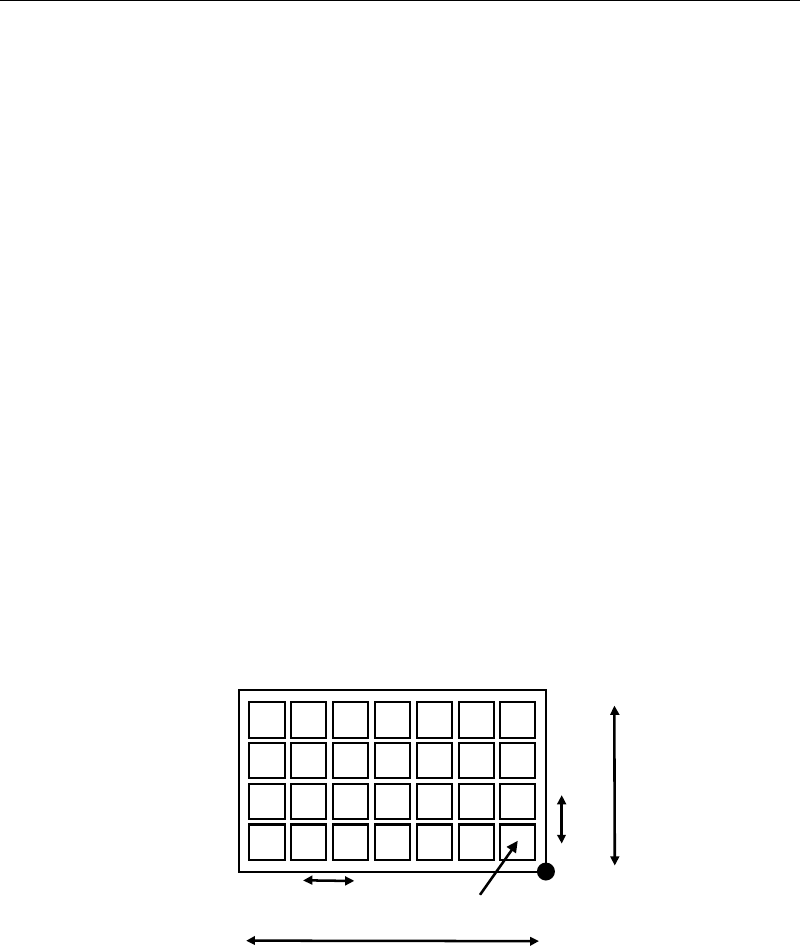
Count X
Pitch X
Pitch Y
Original X/Y
Count Y
Origin
Component Height: Height from the tray bottom to the component upper surface.
* Unit : 0.01mm

Chapter 5 Libraries
5-96
Package Angle: Packaging angle based on the image scanning angle (when viewed
from the machine front). Available settings are 90, 180, -90, and 0.
Counter-clockwise rotation when viewed from above is the positive
angle. Used to link the same components with different packaging
angle.
A
B
To link the component A and B shown above, register [Package
Angle] of B based on [Package Angle] of A. When [Package Angle]
of A is “0”, enter “90” for B. In the pickup data editor, assign A and
B the same component code to link them. With this procedure, you
need not vary the placement angle setting between A and B. The
placement angle setting is based on the image scanning angle.
Error Skip Not used.
Postpone Retry Disabled = Retry disabled, Enabled = Retry enabled. Use of this
function allows retries to be performed collectively at the end of the
program, instead of being performed separately.
However, retries occurring during “postpone retry” will be handled
as normal retries.
To use this function, “Postpone Retry” must be enabled (User
Parameter > Functions(2) > Postpone Retry Step Tray Component
Only).
Setting Tray Library Data (1)
Applies to trays positioned against the positioning blocks of the pallet (in use of a JEDEC tray,
the front positioning blocks).
First, enter [Count X] and [Count Y] settings manually. Then perform teach entry for other
settings (Tool>Teach>TrayTeach).
Action:
Type in [Count X] and [Count Y] settings so they correspond to the location of the third teach
point. In the below example: [Count X]=4, [Count Y]=3.
① Set the tray to a pallet. Set the pallet to the tray feeder. (See Chapter 7.)
② In the tray library editor, click the line to edit. Then click Tool>Teach to open the Teach
dialog box.
③ In [Tray Teach] tab, under [Unit], select a tray feeder. Under [Shuttle Position], select a
pallet stop position. When [Unit] is "MXR", select "Front". When [Unit] is “MX-RT1”,
select “Front” or “Rear” (either will do).
The steps ④ through ⑤ stated below apply only to MX-20, and MXR. As for MX-ST2,
manually set the pallet to the front or rear pickup position.
④ Under [Pallet No.], enter the pallet number.
⑤ Under [Mode], click <Out> button. Then click <Move Pallet> button. The specified pallet
enters the mounter.
When choosing <Move Pallet> button in the Teach dialog box, do not stick head, hands,
or other parts of the body inside the mounter. Serious injury may result. Also make
sure non-operators are a safe distance from the mounter.
Warning