M20_Ope_E - 第247页
Chapter 5 Libraries 5-97 ⑥ Perform three-point teach for th e points illustrated below: Y=3 X=4 Ori g inal p icku p p oint Three teach points are graphically suggested on the Teach dialo g box. While the main teach camer…

Chapter 5 Libraries
5-96
Package Angle: Packaging angle based on the image scanning angle (when viewed
from the machine front). Available settings are 90, 180, -90, and 0.
Counter-clockwise rotation when viewed from above is the positive
angle. Used to link the same components with different packaging
angle.
A
B
To link the component A and B shown above, register [Package
Angle] of B based on [Package Angle] of A. When [Package Angle]
of A is “0”, enter “90” for B. In the pickup data editor, assign A and
B the same component code to link them. With this procedure, you
need not vary the placement angle setting between A and B. The
placement angle setting is based on the image scanning angle.
Error Skip Not used.
Postpone Retry Disabled = Retry disabled, Enabled = Retry enabled. Use of this
function allows retries to be performed collectively at the end of the
program, instead of being performed separately.
However, retries occurring during “postpone retry” will be handled
as normal retries.
To use this function, “Postpone Retry” must be enabled (User
Parameter > Functions(2) > Postpone Retry Step Tray Component
Only).
Setting Tray Library Data (1)
Applies to trays positioned against the positioning blocks of the pallet (in use of a JEDEC tray,
the front positioning blocks).
First, enter [Count X] and [Count Y] settings manually. Then perform teach entry for other
settings (Tool>Teach>TrayTeach).
Action:
Type in [Count X] and [Count Y] settings so they correspond to the location of the third teach
point. In the below example: [Count X]=4, [Count Y]=3.
① Set the tray to a pallet. Set the pallet to the tray feeder. (See Chapter 7.)
② In the tray library editor, click the line to edit. Then click Tool>Teach to open the Teach
dialog box.
③ In [Tray Teach] tab, under [Unit], select a tray feeder. Under [Shuttle Position], select a
pallet stop position. When [Unit] is "MXR", select "Front". When [Unit] is “MX-RT1”,
select “Front” or “Rear” (either will do).
The steps ④ through ⑤ stated below apply only to MX-20, and MXR. As for MX-ST2,
manually set the pallet to the front or rear pickup position.
④ Under [Pallet No.], enter the pallet number.
⑤ Under [Mode], click <Out> button. Then click <Move Pallet> button. The specified pallet
enters the mounter.
When choosing <Move Pallet> button in the Teach dialog box, do not stick head, hands,
or other parts of the body inside the mounter. Serious injury may result. Also make
sure non-operators are a safe distance from the mounter.
Warning
Chapter 5 Libraries
5-97
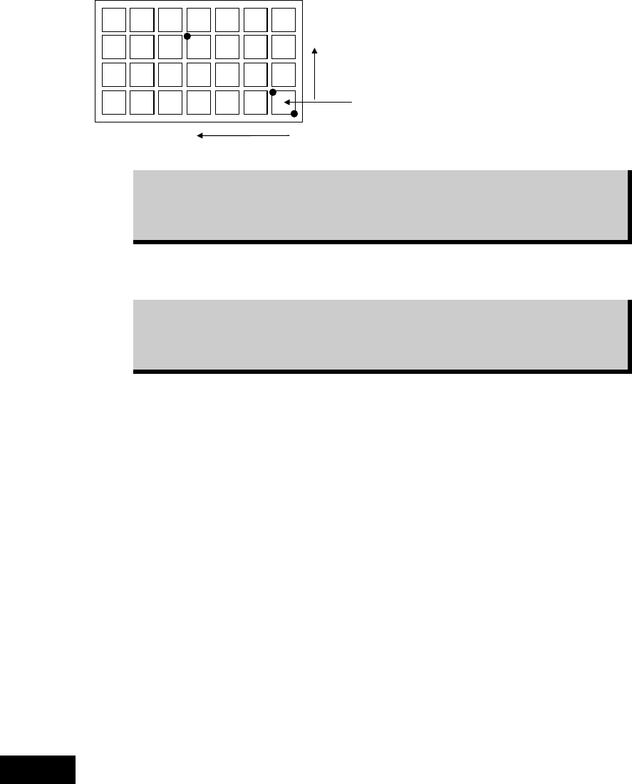
⑥ Perform three-point teach for the points illustrated below:
Y=3
X=4
Ori
g
inal
p
icku
p
p
oint
Three teach points are graphically
suggested on the Teach dialog
box.
While the main teach camera cannot cover the entire tray, it can handle
three-point teach. Within the camera work range, teach the farthest point from
the original pickup point as the third teach point. The third teach point must
correspond to the Count X/Y settings you have entered.
Then the system calculates the original pickup coordinates (Original X/Y) and the component
pitch (Pitch X/Y). The result is displayed in the corresponding fields.
After performing the three-point teach, correct the Count X/Y settings to the
original settings. Otherwise, the system calculates the component count
according to the Count X/Y settings used for the three-point teach, resulting in
component mis-counting.
See the following Caution 1 before operating step
⑧
to
⑬.
⑦ Teach the component height. This teaching is for Z height of the component, therefore the
nozzle needs to be set on a head at first.(recommended nozzle type : No.05 or No.06;
without a rubber.)
⑧ Select “XY axes” in [Axis], and select the head referred to in the previous step in [Head].
Select “1” for both [X Pos.] and [Y Pos.], then click <Trace> to move the head to the
original pickup point.
⑨ Place a sheet of paper with thickness of ordinary photo-copy paper over the component.
Under [Axis], enter “Z axis”. Lower the nozzle slowly toward the component. If necessary,
slow down the axis speed using [Axis Speed] setting. When the nozzle reached the paper,
try to pull the paper to see the nozzle height is proper. When the paper is lightly caught
between the nozzle and component, the nozzle height is best adjusted.
⑩ Subtract 0.1mm from the Z height obtained in the previous step. This means the nozzle
pushes down the component for 0.1mm.Type in the value to TrayLibrary > [Component
Height] field.
⑪ Close the Teach dialog box by clicking <X> button.
⑫ Click File>Save to save the data. Close the tray library editor by clicking <X> button.
The procedures of manual teaching mentioned in steps ⑧ through ⑬ have the risk of collision
of the nozzle against the component. Therefore it is recommended to measure the component
thickness with a caliper and enter the thickness in the Component Height manually.
Caution 1
Chapter 5 Libraries
5-98
z Automatic-component-height teaching by vacuum pressure
Here explains the automatic teaching method in addition to the manual teaching to determine
the component height as mentioned steps ⑧ through ⑬ above. By the automatic teaching, the
mounter checks the vacuum and determines the component height where the vacuum
increases.
Action:
① Attach a nozzle type 05 to the head No. specified in [Head].
Note: Be sure to use a nozzle type 05 which does not have a rubber ring.
② Select “XY axes” in [Axis], and select the head No. which the nozzle type 05 is attached in
[Head]. Select “1” for both [X Pos.] and [Y Pos.], then click the <Trace> to move the head
to the original pickup point.
③ Select “Z-axis” in [Axis], and select the head No. which the nozzle type 05 is attached in
[Head].
Move down the nozzle slowly toward the component surface by confirming visually.
Stop the nozzle when it gets closer to a few millimeters to the component surface.
Note: At this time just close the nozzle to the component surface. Do not let the nozzle touch or hit
the component.
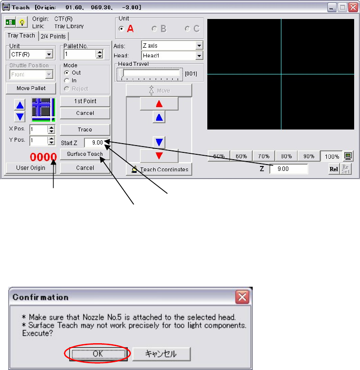
④ Enter this height of step ③ in [Start Z].
⑤ Click the <Surface Teach> button.
The following dialog box appears. Press the <OK> button.
Then the nozzle automatically starts moving down slowly from the height of the [Start Z]
with vacuum is on.
It shows the head [Vacuum].
Click the <Surface Teach> button.
Enter the height in [Start Z].