M20_Ope_E - 第251页
Chapter 5 Libraries 5-101 5-2-4 Tray Orientation Check The tray orientation check function finds the or ientation of component trays and prevents from setting trays in wrong orientation. The main teac h camera captures a…

Chapter 5 Libraries
5-100
Setting Tray Library Data (2)
This method applies to trays not positioned against the positioning blocks of the pallet. In this
case, you must notify the system of the offset of the tray.
First, enter [Count X] and [Count Y] settings manually. Then perform teach entry for other
settings (Tool>Teach>TrayTeach).
Action:
Type in [Count X] and [Count Y] settings so they correspond to the location of the third teach
point. In the below example: [Count X]=4, [Count Y]=3.
① Set the tray to a pallet. Set the pallet to MX-40. (See Chapter 7.)
② Open the Board Data dialog box (Program>File>BoardData) and enter the board size
correctly. (for the case of MX-20 and MXR)
③ Click Library>Pallet Library to open the pallet library editor.
④ Click the X Offset or Y Offset field of the pallet. ([X Offset] and [Y Offset] settings must be
entered beforehand.)
⑤ Click Tool>Teach to open the Teach dialog box.
When choosing <Move Pallet> button in the Teach dialog box, do not stick head, hands,
or other parts of the body inside the mounter. Serious injury can result. Also make sure
non-operators are a safe distance from the machine.
⑥ In [Tray Teach] tab, under [Unit], select a tray feeder. Under [Shuttle Position], select a
pallet stop position. When [Unit] is "MXR", select "Front". When [Unit] is “MX-RT1”,
select “Front” or “Rear” (either will do).
The steps 7 through 8 stated below apply only to MX-40, MX-20, and MXR. As for MX-ST2,
manually set the pallet to the front or rear pickup position.
⑦ Under [Pallet No.], enter the pallet number.
⑧ Under [Mode], click <Out> button. Then click <Move Pallet> button. The specified pallet
moves into the mounter.
⑨ Click <Trace> button. The main teach camera moves toward above the front right corner
of the tray.
⑩ Open the tray library editor. Click the line to edit. Click <User Origin> button in the Teach
dialog box.
Then follow the steps 7 through the end of Setting Tray Library Data (1) in the previous section.
Tray Trace Feature
This feature allows the specified head to move to the specified tray component.
Select a line to trace in the tray library editor. Then open the Teach dialog box. Then specify the
tray feeder to [Unit], pallet stop position to [Shuttle Position], pallet number to [Pallet No.], and
component position to [X Pos.] and [Y Pos.]. Click <Trace> button to execute.
Note: Manual entry of the tray library data using ready-to-use database or actual measurements is
also available.
Warning
Chapter 5 Libraries
5-101
5-2-4 Tray Orientation Check
The tray orientation check function finds the orientation of component trays and prevents from
setting trays in wrong orientation. The main teach camera captures an indexed part (chamfered
corner) of a component tray and judges the tray orientation set on the tray feeder.
Application
The tray orientation check function is available for the following tray feeders.
z CTF
z FTF
Setting
Menu: System > Tray Library
Action:
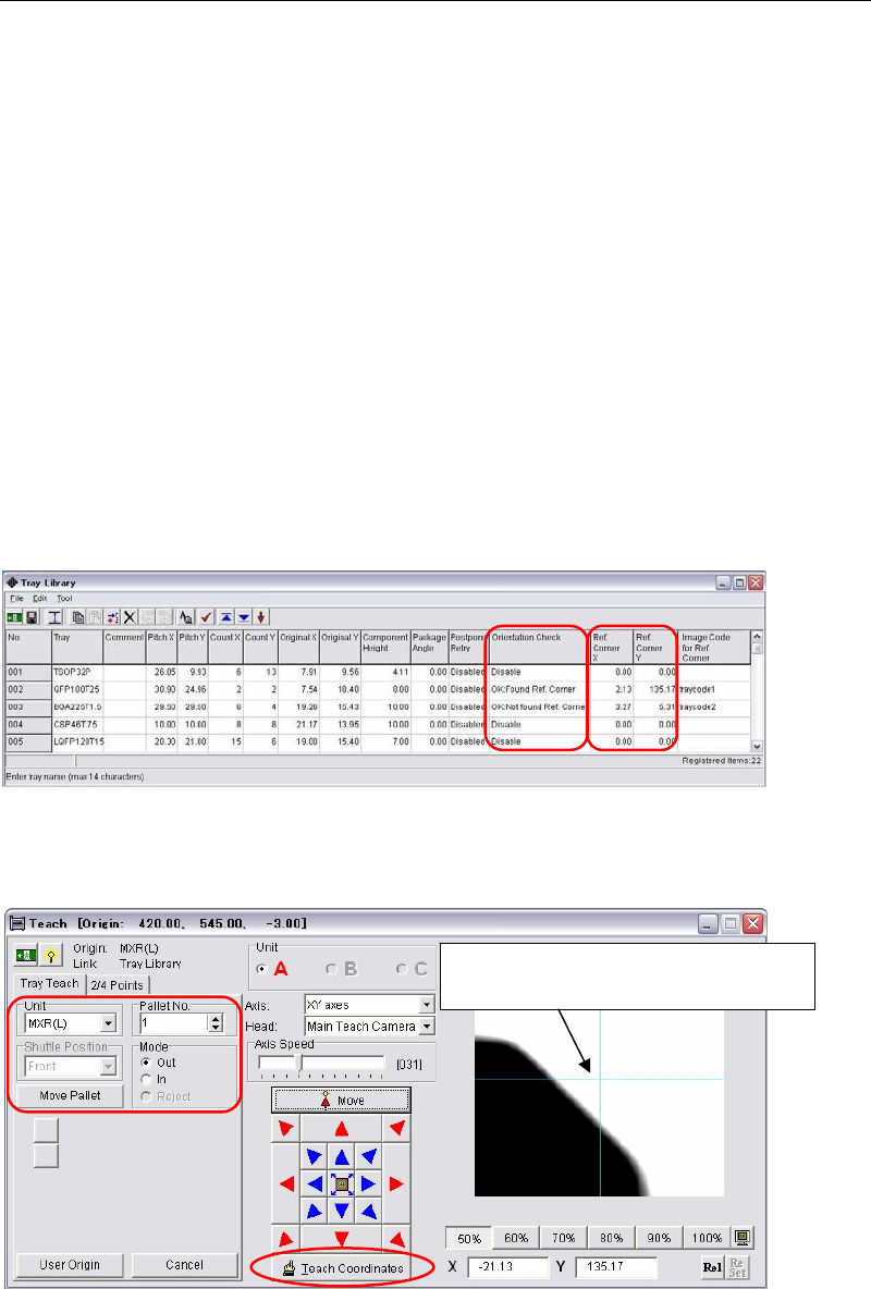
① The way of the bad-mark image-capture is applied to this tray orientation check function.
In the [Orientation Check] column, select the logics to find tray reference corners, ”OK:
Found Ref. Corner” or “OK: Not found Ref. Corner”.
Usually Use ”OK: Found Ref. Corner”.
② Click a [Ref. Corner X] or a [Ref. Corner Y] cell of the tray data to edit. The teach window
below appears.
③ Make sure the tray model in the [Unit] and the pallet No. are correct. Pull out the pallet.
Then teach the indexed part (chamfered corner) and click the [Teach Coordinates] to enter
the coordinates.
Teach the indexed part (chamfered
corner) and determine the coordinates.
Chapter 5 Libraries
5-102
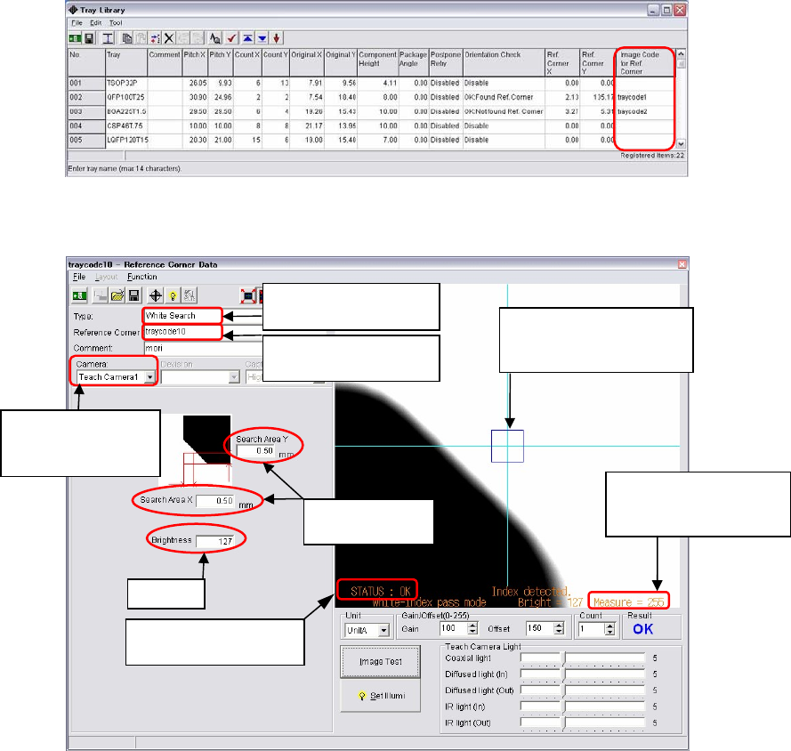
④ Double click the blank cell of the [Image Code for Ref. Corner].
⑤ The image data edit window below appears.
⑥ Create the image data of the reference corner as same as a bad mark.
z Select the center color of the monitor for the [Type]. When the tray color is black,
select "White Search".
z Input the image code name.
z Both the teach camera 1 (main teach camera) and the teach camera 2 (aux. teach
camera) are available. (The default setting is the teach camera 1.)
z Input the image capture area. Input the lengths in the [Search Area X] and the [Search
Area Y].
(Recommended length: 0.5 to 1.0mm)
z Enter the threshold of black or white in the [Brightness]. (Standard: 127)
z Adjust the gain and offset values so that the tray image is displayed in black and the
background is displayed in white (for a black tray).
⑦ Execute image test. When the image test ends successfully and “OK” appears, write down
the value of “Measure”. (Example: Measure=255)
The search area is
created at the indexed
part (chamfered corner).
Normally enter
0.5 to 1.0mm.
Std. 127
Enter an image data
name.
Select “White Search”
for a black tray.
Write down “Measure”
value, the result of the
image test.
Make sure the result
of
Image Test is “OK”.
Teach Camera1 and
Teach Camera2 are
selectable.