M20_Ope_E - 第252页
Chapter 5 Libraries 5-102 ④ Double click the blank cell of the [Image Code for Ref. Corner]. ⑤ The image data edit window below appears. ⑥ Create the im age data of the refere nce corner as same as a bad mark. z Select t…
Chapter 5 Libraries
5-101
5-2-4 Tray Orientation Check
The tray orientation check function finds the orientation of component trays and prevents from
setting trays in wrong orientation. The main teach camera captures an indexed part (chamfered
corner) of a component tray and judges the tray orientation set on the tray feeder.
Application
The tray orientation check function is available for the following tray feeders.
z CTF
z FTF
Setting
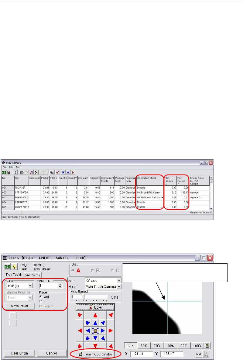
Menu: System > Tray Library
Action:
① The way of the bad-mark image-capture is applied to this tray orientation check function.
In the [Orientation Check] column, select the logics to find tray reference corners, ”OK:
Found Ref. Corner” or “OK: Not found Ref. Corner”.
Usually Use ”OK: Found Ref. Corner”.
② Click a [Ref. Corner X] or a [Ref. Corner Y] cell of the tray data to edit. The teach window
below appears.
③ Make sure the tray model in the [Unit] and the pallet No. are correct. Pull out the pallet.
Then teach the indexed part (chamfered corner) and click the [Teach Coordinates] to enter
the coordinates.
Teach the indexed part (chamfered
corner) and determine the coordinates.
Chapter 5 Libraries
5-102
④ Double click the blank cell of the [Image Code for Ref. Corner].
⑤ The image data edit window below appears.
⑥ Create the image data of the reference corner as same as a bad mark.
z Select the center color of the monitor for the [Type]. When the tray color is black,
select "White Search".
z Input the image code name.
z Both the teach camera 1 (main teach camera) and the teach camera 2 (aux. teach
camera) are available. (The default setting is the teach camera 1.)
z Input the image capture area. Input the lengths in the [Search Area X] and the [Search
Area Y].
(Recommended length: 0.5 to 1.0mm)
z Enter the threshold of black or white in the [Brightness]. (Standard: 127)
z Adjust the gain and offset values so that the tray image is displayed in black and the
background is displayed in white (for a black tray).
⑦ Execute image test. When the image test ends successfully and “OK” appears, write down
the value of “Measure”. (Example: Measure=255)
The search area is
created at the indexed
part (chamfered corner).
Normally enter
0.5 to 1.0mm.
Std. 127
Enter an image data
name.
Select “White Search”
for a black tray.
Write down “Measure”
value, the result of the
image test.
Make sure the result
of
Image Test is “OK”.
Teach Camera1 and
Teach Camera2 are
selectable.
Chapter 5 Libraries
5-103
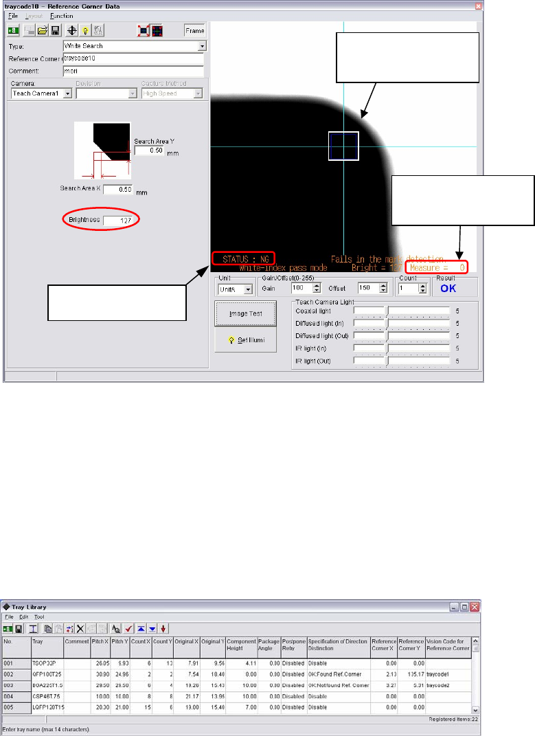
⑧ Put the tray in the reverse direction. Make sure the tray covers the search area. If the tray
locates out of the search area, repeat the procedures from step ③.
Execute image test to make sure the result will be “NG”.
⑨ Write down the value of “Measure”. (Example: Measure=0)
When the center value of step ⑦ and ⑨ is close to 127 entered in the [Brightness], it means
the mounter recognizes black and white correctly.
Center value = Measure value at ⑦ + Measure value at ⑨ /2
(Ex.: Center value (255 + 0)/2 = 127)
If the calculated value is not close to 127, enter the actually calculated value in the
[Brightness].
⑩ Save the image data. Close the image data edit window.
⑪ Right-click the [Image Code for Ref. Corner] and select the created image data.
Make sure the search
area locates within the
tray corner.
Write down “Measure”
value, the result of the
image test.
Make sure the result
of
Image Test is “NG”.