M20_Ope_E - 第256页
Chapter 5 Libraries 5-106 5-2-6 Feeder Library (Feeder Data) Menu: Program>FeederData Program>PickupData>Feeder/Pallet>FeederData Window: For the current version, only feeder name is required for [Feeder] fie…
Chapter 5 Libraries
5-105
5-2-5 Packaging Library (Package Data)
Menu: Program>PackageData
Program>PickupData>Package/Tray>PackageData
Window:
File>Save: Saves the edited data.
Packaging: Packaging name. Serves to relate the packaging library and the
pickup data editor (program editor).
Pitch: Normally not used.
When you want two or more times of feeding action for a pickup
operation, make this setting in addition to “Feeder Pitch” setting
(see the feeder library).
Example: To feed components (component pitch: 8mm) using a
F1-84 feeder (feeder pitch: 4mm), set this item to 8.00. Since the
feeder pitch for the F1-84 feeder is set to 4.00 (4mm), components
will be jogged twice automatically when they are picked up, when
using this packaging code for the F1-84 feeder.
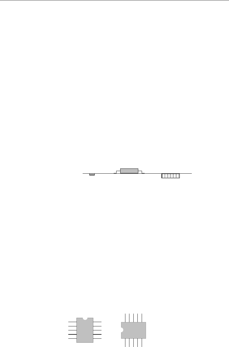
Height: Packaging height based on the pickup Z origin. The height for tape
feeders can be described as below:
Z=0
Punched tape
Adhesive tape
Embossed tape
Punched tape: Tape thickness.
Adhesive tape: Component height - 1.5mm. (-1.5mm is the
compensation value for adhesive-tape-specific feeders.) For
example, when the component is 2mm thick, 0.5mm shall be
entered to [Height].
Embossed tape: 0.
For precise measurement, teach the Z coordinate of the component
in the pickup data editor.
Stick feeder: 0
For precise measurement, teach the Z coordinate of the component
in the pickup data editor.
* Increment : 0.01mm
Package Angle: Packaging angle based on the image scanning angle (when viewed
from the machine front). Available settings are 90, 180, -90, and 0.
Counter-clockwise rotation when viewed from above is the positive
angle. Used to link the same components with different packaging
angle.
A
B
To link the component A and B shown above, register [Package
Angle] of B based on [Package Angle] of A. When [Package Angle]
of A is “0”, enter “90” for B. In the pickup data editor, assign A and
B the same component code to link them. With this procedure, you
need not vary the placement angle setting between A and B. The
placement angle setting is based on the image scanning angle.

Chapter 5 Libraries
5-106
5-2-6 Feeder Library (Feeder Data)
Menu: Program>FeederData
Program>PickupData>Feeder/Pallet>FeederData
Window: For the current version, only feeder name is required for [Feeder] field. Enter this name to
PickupData>[Feeder/Pallet]. Leave other settings as default.
File>Save: Saves the edited data.
Feeder: Names of PS / F1-series feeders can be provided as available
choices. Click the right mouse button to present the list.
Lot No.: Planned for future use.
Feeder Code: Do not change.
Feed Pitch: Use the default setting.
Feed Height: Planned for future use.
X Offset: Use the default setting.
Y Offset: Use the default setting.
Setting for Multi-stick Feeder (PS-MS3)
The PS-MS3 mufti-stick feeder has multiple pickup points. Their positions are defined by
coordinate offsets from the coordinate values of the station on which the PS-MS1 is set.
Enter feeder names from PS-MS3-A to PS-MS-I that correspond to the pickup points in the
pickup data. Then, enter offsets of each pickup point to [X Offset] and [Y Offset] of this feeder
data.
Setting for Multi-stick Feeder (MSF-1)
The MSF-1 mufti-stick feeder has multiple pickup points. Their positions are defined by
coordinate offsets from the coordinate values of the station on which the MSF-1 is set.
Enter feeder names from MSF-01 to MSF-16 that correspond to the pickup points in the pickup
data. Then, enter offsets of each pickup point to [X Offset] and [Y Offset] of this feeder data..

Chapter 5 Libraries
5-107
5-3 Copying Library
5-3-1 Copying User Library and Master Library
A user library and master library are provided for various data such as component data, feeder
data, package data, pallet data, tray data, and nozzle data.
In the user library, you can store the data you have created to use it for other programs. The
master library consists of read-only typical data loaded at the factory prior to shipment. Both
user library and master library are normally hidden. Any desired data in the master library can
be copied into the user library.
Menu: Program>ComponentData/FeederData/PackageData/PalletData/TrayData/NozzleData
Action:
① In each data window, click [Tool]>[Search Library] or the [Search Library] icon.
Or, press the F3 key on the keyboard.
② The user library and master library appear in the lower part of the window.
The user library is shown in white and the master library in gray.
③ Copy data by dragging and dropping it between the data list in the upper part and the
user library or master library in the lower part.
④ You can also copy data from the master library to the user library by dragging and
dropping it.
Note: If data with the same code name exists in the copy destination, that data will be overwritten.
So, it is recommended to change (rename) the code name after the component data has been
copied.
Note: No data can be copied to the master library.
Drag and drop desired
data to copy it.
Master Library (gray)
Various data
User Librar
y
(white)
[Search Library] icon