M20_Ope_E - 第261页
Chapter 6 Coplanarity Checker 6-1 Chapter 6 Coplanarity Checker 6-1 Specifications 6-2 Data Settings 6-3 Maintenance
Chapter 5 Libraries
5-110
③ Select image data you want to copy in the [Master Library:] portion on the left of this
window.
Additionally, you can drag multiple image data lines using the mouse to select them.
④ Click [Copy] at the lower left portion of the window.
The image data is then copied to the [Use Library:] portion on the right of the window.
⑤ Close this window.
⑥ The image data that has been copied is then added to the [Select Component] window
described in step ①.
Note: If data with the same code name is already present in the copy destination, that data will be
overwritten.
So, it is recommended to change (rename) the code name after the image data has been copied.
Chapter 6 Coplanarity Checker
6-1
Chapter 6
Coplanarity Checker
6-1 Specifications
6-2 Data Settings
6-3 Maintenance
Chapter 6 Coplanarity Checker
6-2
6-1 Specifications
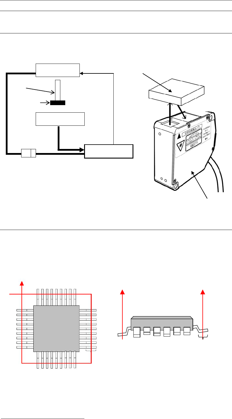
6-1-1 System Configuration
The chart below shows System Configuration of “Coplanarity Checker”device.
6-1-2 Coplanarity Detecting Sequence
1) In advance to detect Coplanarity, a component image is recognized to correct the pickup
offset.
2) Coplanarity Checker irradiates the laser at the middle length of lead foot to make the laser
diffused-reflected and then measure all the lead height of a component.
3) In comparison to the assumed plane
1
, leads height offsets are checked. If there are excess
lead offsets to “Lead Height Tolerance”, errors will occur.
1
Assumed plane is an average height of all the detected leads of a component.
Target Comp.
Component
Laser Sensor
Laser Sensor
Laser Amp.
Mounter
Sensor Cable
DC Power
DC24V
Nozzle
Transmitting
Receiving
Coplanarity Checker
Top View Side View
Lead Foot
Lead Foot