M20_Ope_E - 第263页
Chapter 6 Coplanarity Checker 6-3 6-1-3 Laser Sensor Specifications The chart below shows the laser sensor speci fications for the Coplanarity Checker. Items Specifications Lead height detecting accuracy ± 5 μ m Laser wa…
Chapter 6 Coplanarity Checker
6-2
6-1 Specifications
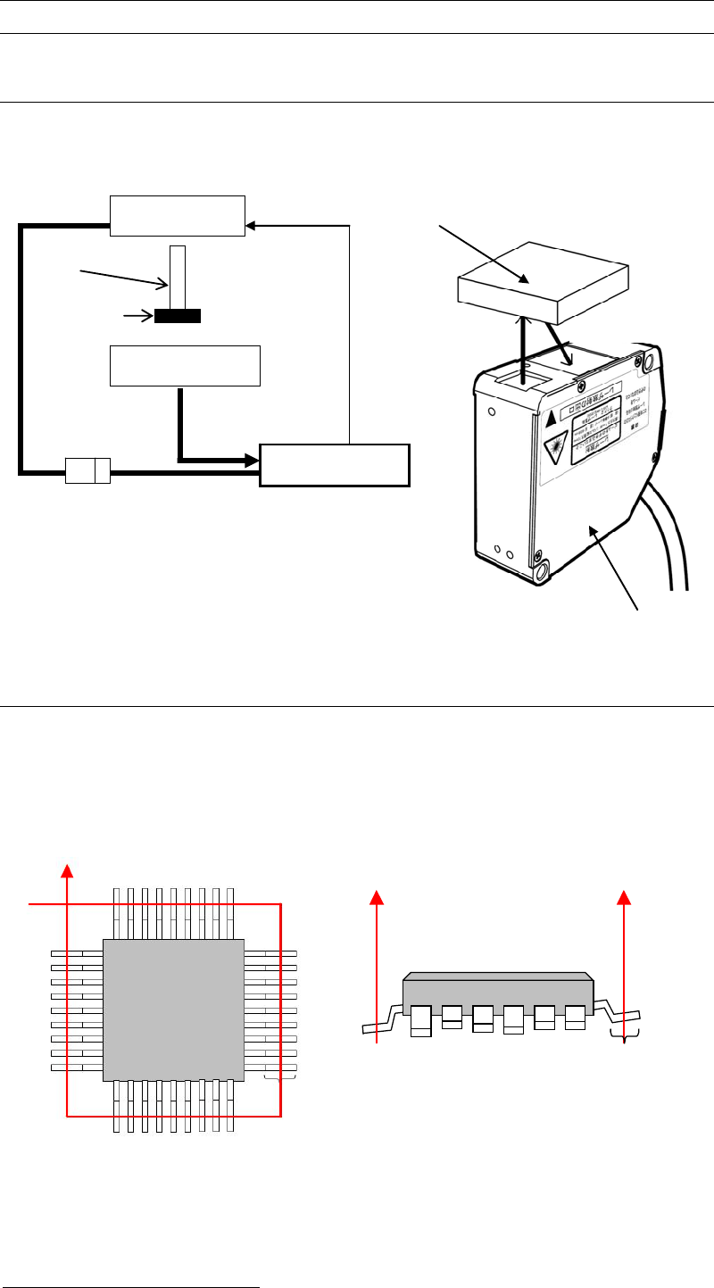
6-1-1 System Configuration
The chart below shows System Configuration of “Coplanarity Checker”device.
6-1-2 Coplanarity Detecting Sequence
1) In advance to detect Coplanarity, a component image is recognized to correct the pickup
offset.
2) Coplanarity Checker irradiates the laser at the middle length of lead foot to make the laser
diffused-reflected and then measure all the lead height of a component.
3) In comparison to the assumed plane
1
, leads height offsets are checked. If there are excess
lead offsets to “Lead Height Tolerance”, errors will occur.
1
Assumed plane is an average height of all the detected leads of a component.
Target Comp.
Component
Laser Sensor
Laser Sensor
Laser Amp.
Mounter
Sensor Cable
DC Power
DC24V
Nozzle
Transmitting
Receiving
Coplanarity Checker
Top View Side View
Lead Foot
Lead Foot
Chapter 6 Coplanarity Checker
6-3
6-1-3 Laser Sensor Specifications
The chart below shows the laser sensor specifications for the Coplanarity Checker.
Items Specifications
Lead height detecting accuracy
±5μm
Laser wavelength 650nm
Laser maximum output power 4.8mW
Laser class 3R
Laser measurement range
30±5mm
Note: In case that leads are bent horizontally, the Coplanarity Checker may not be able to detect the
bent leads correctly.
Note: The laser sensor works only when the mounter handles the components which Coplanarity
Check function is selected and activated while the mounter is running. When the mounter
pauses, the laser sensor pauses either.
When handling Coplanarity Checker, pay careful attention to it as hereafter.
• Do not soil the surface of laser transmitting/receiving windows with water, oil, or
fingerprints to prevent it from beam refraction. Keep the laser transmitting/receiving
windows away from dirt or dust to prevent it from blocking the beam as well.
• Do not let sunlight or ambient light such as the same wavelength light directly into the
receiving window.
• Do not look at laser beam directly and also do not look at laser reflected by a mirror.
6-1-4 Laser Amplifier Specifications
Items Specifications
Power requirements
24V DC±10% (supplied from mounter.)
Maximum current consumption 500mA or less
6-1-5 Detecting Time
Items Coplanarity Detecting Time
10mm square 1.35 sec.
15mm square 1.50 sec.
30mm square 2.00 sec.
45mm square 2.75 sec.
Chapter 6 Coplanarity Checker
6-4
6-1-6 Available Components for the check
Coplanarity Checker can handle QFP, LQFP, TQFP, SOP, SSOP, TSOP, TTSOP, and connectors.
But it is not possible to handle ball components or odd-shaped lead components.
The maximum component size is equal to the specifications of your mounter.
Maximum number of leads: 400 leads
Missing leads: Supported
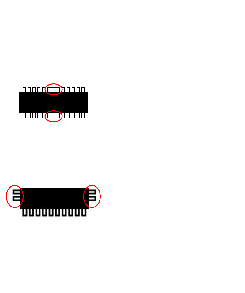
Thick lead: Not supported
Components that have any wider leads than the others
cannot be checked. (inside the red circles)
Connector’s lead: One side/both sides leads connectors are supported.
(with some limitations)
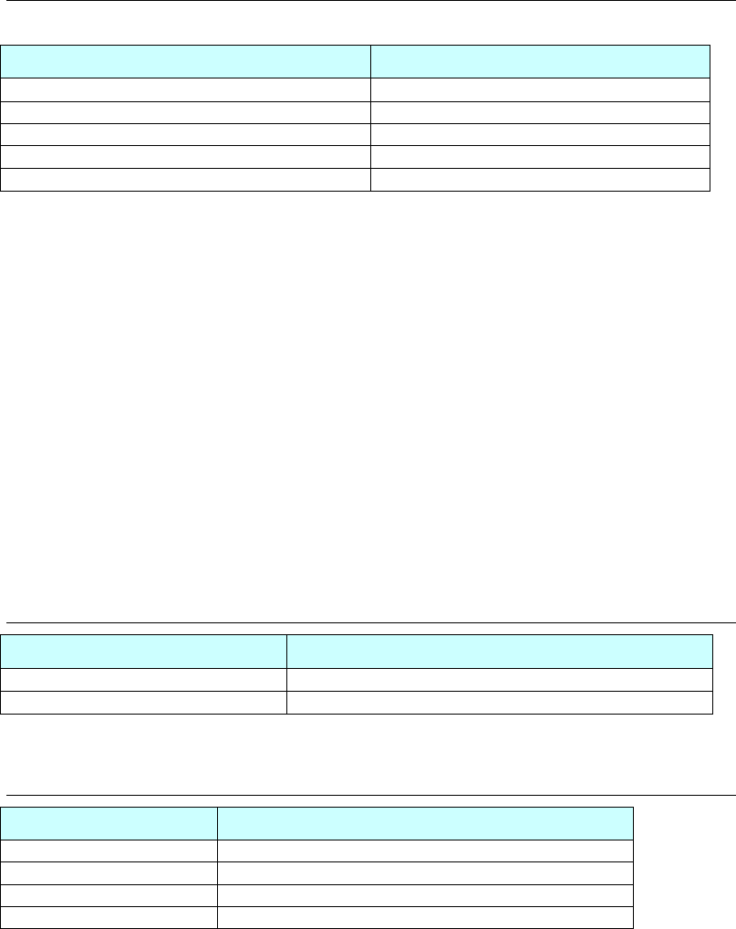
6-1-7 Pass/Fail Criteria
Pass or Fail is resulted comparing Lead offsets in Z-axis direction (coplanarity) to Assumed
plane of the component.
6-1-8 Restriction for production
The maximum number of Coplanarity Check data for a program;
The maximum number of Image Libraries with Coplanarity Check data for one program is 99
records.
In case of the component like the left drawing,
leads at both sides (inside of red circle) cannot
be checked.