M20_Ope_E - 第267页
Chapter 6 Coplanarity Checker 6-7 SOP/QFP Lead Count X Component Size X Lead Pitch X Lead Width Component Size Y Component Size X Connector Lead Row Component Size Y Lead Width Lead Pitch Lead Count X Component Size X Le…
Chapter 6 Coplanarity Checker
6-6
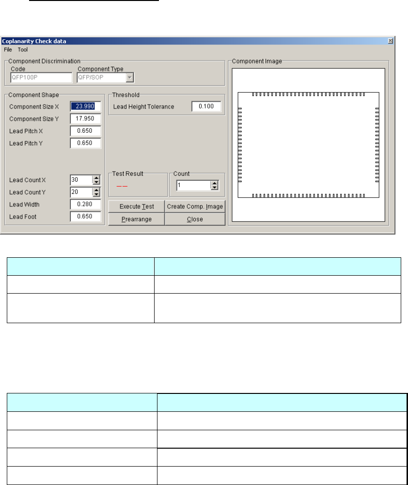
4) Open [Coplanarity Check data].
Coplanarity Check data consists of settings such as Component Shape, Threshold, etc. See the
followings for details of each setting.
■Component Discrimination
Items Descriptions
Code Image Library code name is displayed.
Component Type
Component Type is displayed.
(QFP/SOP/Connector)
■Component Shape
Input values in items below. (Items differ for each Component type.)
Each item in Component Shape is set automatically from Image Library data when Coplanarity
Check data window is opened. If the sizes are not accurate, Coplanarity Check would fail. In
this case enter accurate sizes from the component design dimensions.
Items Comment
Component Size X (Note-1) Lead Count X, at one side
Component Size Y (Note-1) Lead Count Y, at one side
Lead Pitch X Lead Width
Lead Pitch Y Lead Foot
Note-1: “Component Size” is outer dimension of the component.
Note: Image Library of Connector does not have some values such as Component Size X/Y etc.
Those values are acquired by Mounter’s calculation automatically when Coplanarity
Check data is newly created. If the calculated value is not equal to the designed dimensions
or actual measured dimensions, correct the values manually. (The figures below are
internally used to acquire connector’s dimensions by values in Image Library.)
Reference: Figures to acquire connector’s dimension
(“”: Items in Coplanarity Check data, [ ]: Items in Image Library)
“Lead Width” = [Lead Pitch] x 0.4
“Lead Count” = ([End Lead Pitch] / [Lead Pitch]) + 1
“Component Size X” or”Component Size Y” (longer side) = [Lead Row]
The initial values are set by the figures above, but correct them if necessary. For example, in
case of Connector, “Component Size” (Outer Dimension) should be bigger than “Lead Row”
actually.
Chapter 6 Coplanarity Checker
6-7
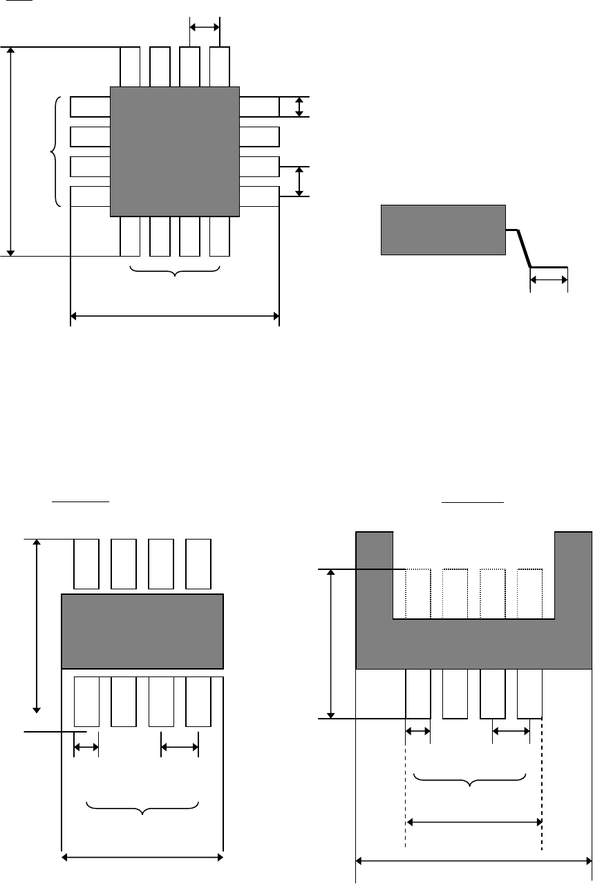
SOP/QFP
Lead Count X
Component Size X
Lead Pitch X
Lead Width
Component
Size Y
Component Size X
Connector
Lead Row
Component
Size Y
Lead Width
Lead Pitch
Lead Count X
Component Size X
Lead Length
Lead Count X
Lead Pitch Y
Lead Width
Lead Pitch X
QFP
Component Size Y
Lead Count Y

Chapter 6 Coplanarity Checker
6-8
■Threshold
Item Description
Lead Height
Tolerance
Enter a Threshold to evaluate whether the component is good or bad.
Component coplanarity is judged in comparison with Assumed Plane
1
calculated from the lead heights, to the biggest offset lead of upper or
lower direction. Default setting is 0.10.
Note: Enter “Lead Height Tolerance” in consideration of solder thickness, etc.
■Advanced Setting for Coplanarity Check data
Click [Coplanarity Check data]-[Tool]-[Advanced Setting] to open [Coplanarity Check Data
Advanced setting] window.
Item Description Range
Sampling Cycle
Set a Laser projection cycle.
10 to 2000 [micro sec.]
(Default: 40 micro sec.)
Measurement Height
Offset
Set a component height for
measurement.
0 (default)
Scanning Speed Set a scanning speed for measurement. 300 (default)
Filter Level
Set a smoothing level of measurement
data.
7 (default)
Slice Level Set a threshold for error judgment. 10 (default)
Distance between
Two sides
Set an invalid length between two sides. 500 (default)
Measurement valid
Width
Set a valid range of measurement data. 0.150 (default)
* Use default settings (initial values) for Advanced Settings normally.
Only in case of Bumpered QFPs as shown below, input 4.5 in “Measurement Height Offset”.
1
Assumed Plane is an average height of all the detected leads of a component.
Lead Height
Height of the most bent lead
Assumed Plane Height