M20_Ope_E - 第268页
Chapter 6 Coplanarity Checker 6-8 ■ Threshold Item Description Lead Height Tolerance Enter a Threshold to evaluate whether the component is good or bad. Component coplanarity is judged in comparison with Assumed Plane 1 …
Chapter 6 Coplanarity Checker
6-7
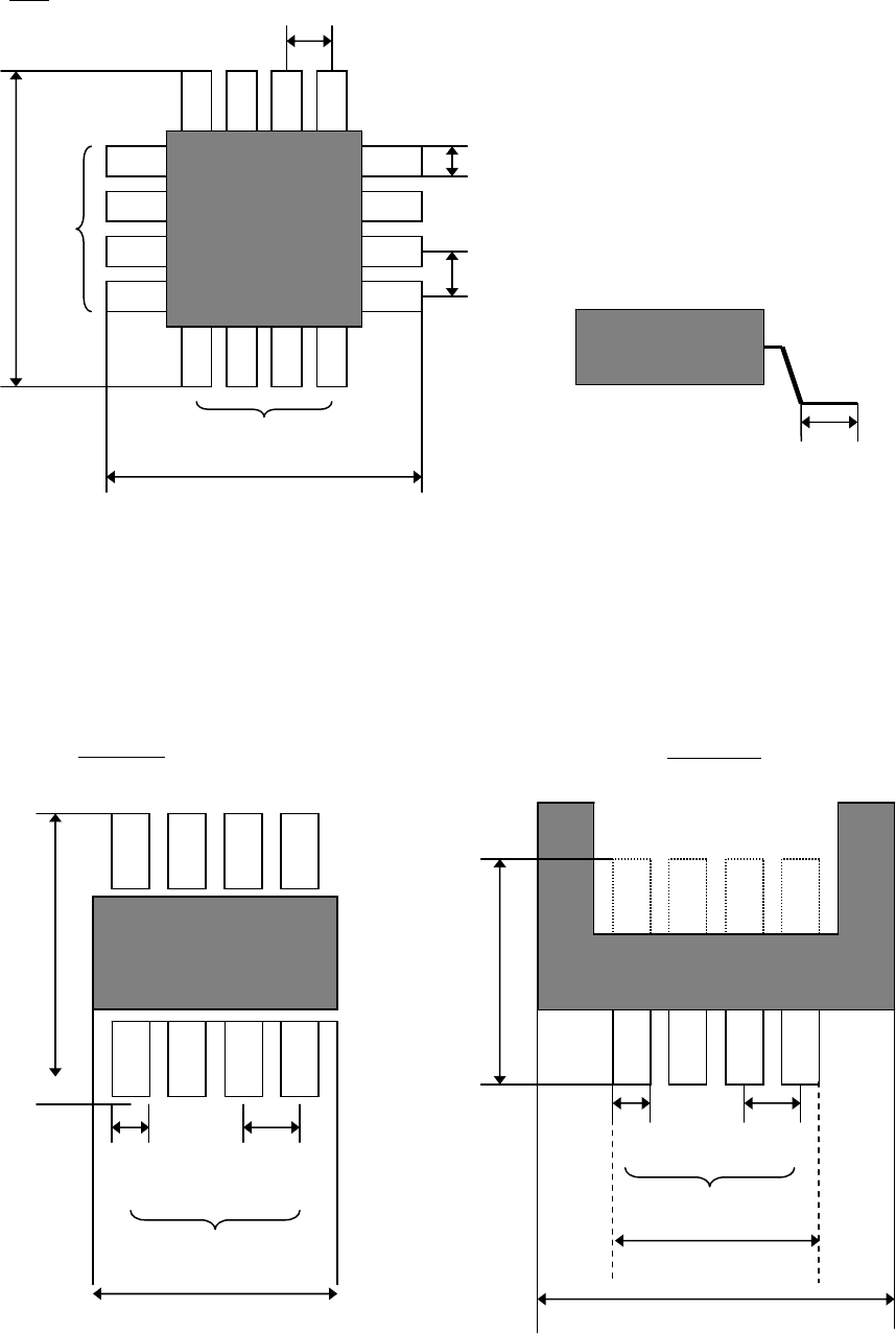
SOP/QFP
Lead Count X
Component Size X
Lead Pitch X
Lead Width
Component
Size Y
Component Size X
Connector
Lead Row
Component
Size Y
Lead Width
Lead Pitch
Lead Count X
Component Size X
Lead Length
Lead Count X
Lead Pitch Y
Lead Width
Lead Pitch X
QFP
Component Size Y
Lead Count Y

Chapter 6 Coplanarity Checker
6-8
■Threshold
Item Description
Lead Height
Tolerance
Enter a Threshold to evaluate whether the component is good or bad.
Component coplanarity is judged in comparison with Assumed Plane
1
calculated from the lead heights, to the biggest offset lead of upper or
lower direction. Default setting is 0.10.
Note: Enter “Lead Height Tolerance” in consideration of solder thickness, etc.
■Advanced Setting for Coplanarity Check data
Click [Coplanarity Check data]-[Tool]-[Advanced Setting] to open [Coplanarity Check Data
Advanced setting] window.
Item Description Range
Sampling Cycle
Set a Laser projection cycle.
10 to 2000 [micro sec.]
(Default: 40 micro sec.)
Measurement Height
Offset
Set a component height for
measurement.
0 (default)
Scanning Speed Set a scanning speed for measurement. 300 (default)
Filter Level
Set a smoothing level of measurement
data.
7 (default)
Slice Level Set a threshold for error judgment. 10 (default)
Distance between
Two sides
Set an invalid length between two sides. 500 (default)
Measurement valid
Width
Set a valid range of measurement data. 0.150 (default)
* Use default settings (initial values) for Advanced Settings normally.
Only in case of Bumpered QFPs as shown below, input 4.5 in “Measurement Height Offset”.
1
Assumed Plane is an average height of all the detected leads of a component.
Lead Height
Height of the most bent lead
Assumed Plane Height
Chapter 6 Coplanarity Checker
6-9
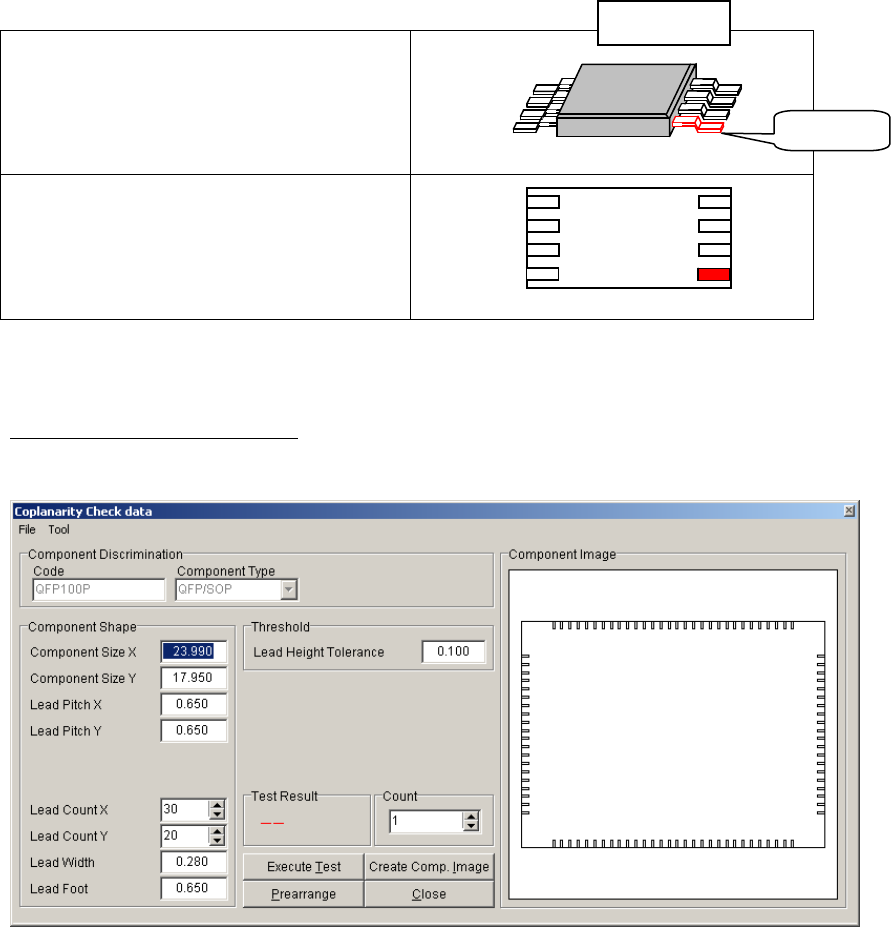
■Component Image
Component image is displayed in [Component Image] window in [Coplanarity
Check data] screen. In case leads are failed in Coplanarity Check test, they are
indicated in red color.
Component Packaging angle
(When facing to Mounter)
Component image
(in Coplanarity Check edit screen)
Note: The error leads are indicated in red color and the missing leads are indicated in light blue
color.
5) Execute Coplanarity Check test.
After all necessary items are entered, execute Coplanarity Check test as follows:
1 Click [Create Com. Image] button to display the component image.
The image is drawn by [Component Shape] data. Compare the image with the actual
component to check whether the [Component Shape] data are correct. (Component Size
X/Y is defined as outer length of Lead, and the Lead part is overlaid with the mold part in
the image drawing.)
2 Confirm the component is still attached to the nozzle since the step “2) Do Image Test”. If
the component is not attached, do the step “2) Do Image Test” again.
3 Click [Execute Test] button to do Coplanarity Check test.
4 In [Test Result] box, the result OK or NG is displayed. If the result is NG, check the error
status by a message and a [Component Image] display.
NG Lead
Ex.:SOP