M20_Ope_E - 第27页
Chapter 1 General 1-9 Note: Moving directions of the arrow keys reverse in the [Axis], [Teach], [Load Board], and [Conveyor Width] windows. The displayed image in the Teach window is al so reversed from top to down and r…
Chapter 1 General
1-8
1-1-1-4 Rear-side Operation
This option allows for operation on the rear side of the mounter in the same way as on the front side. The
option is configured with the display, keyboard, mouse, and the control switches.
z The MAIN
switch locates only on the front side. Turn the mounter of/off from the front side.
z When the system is turned on, the front ACTIVE
switch lights up and the front side is enabled
initially. To enable the rear side, press the ACTIVE
switch on the rear side. The rear ACTIVE
switch lights up.
z To switch the operation side, press the front or rear ENABLE
switch which you want to operate. The
operation on the selected side is enabled and the ACTIVE
switch lights up.
z The front and rear monitors display the same contents.
Note: Both the front and rear EMERGENCY STOP
switches are always enabled irrespective of which the
ACTIVE
switch is enabled.
Note: Connect the keyboard and the mouse before turning on the system. Do not connect/disconnect the
keyboard or the mouse after the system has been turned on.
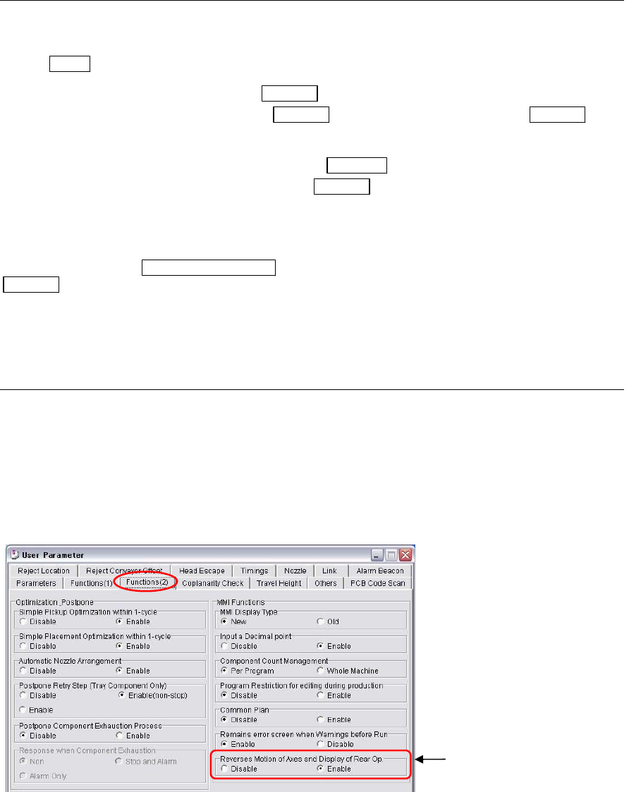
1-1-1-5 Setting for Rear-side Operation
When you operate the mounter from the rear side, the travel directions of X, Y, Theta axes, PCB flow, and
the automatic conveyor width setting look opposite in comparison when you operate from the front.
By selecting the reverse function as below, the arrow keys move the axes as it actually appears on the rear
display in the [Axis], [Teach], [Load Board], and [Auto Conveyor Width Set] windows. For instance, by
selecting the left arrow key from the rear, the X axis moves toward the axis origin when using the reverse
function. Normal operation, the left arrow key causes the X axis to move away from the axis origin.
Menu: System>UserParameter>Functions(2)
Enable the “Reverses Motion
of Axes and Display of Rear
O
p
.”
Chapter 1 General
1-9
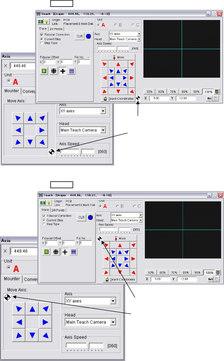
Note: Moving directions of the arrow keys reverse in the [Axis], [Teach], [Load Board], and [Conveyor Width]
windows. The displayed image in the Teach window is also reversed from top to down and right to left.
Note: Please note that the ANC station numbers and their order in the [Nozzle Info.] does not change even if
the reverse function is selected.
Teach and Axis windows of Front-side operation
ACTIVE
switch on the front side is pressed.
Teach and Axis windows of Rear-side operation
ACTIVE
switch on the rear side is pressed.
Note: The origin mark appears in the windows only when this reverse function is selected in the user
parameter.
The origin mark appears in the
lower right in the Teach and Axis
windows. It means the machine
origin is at the lower right as viewed
from the front.
The origin mark appears in the
upper left in the Teach and Axis
windows. It means the machine
origin is at the upper left as viewed
from the rear.
Chapter 1 General
1-10
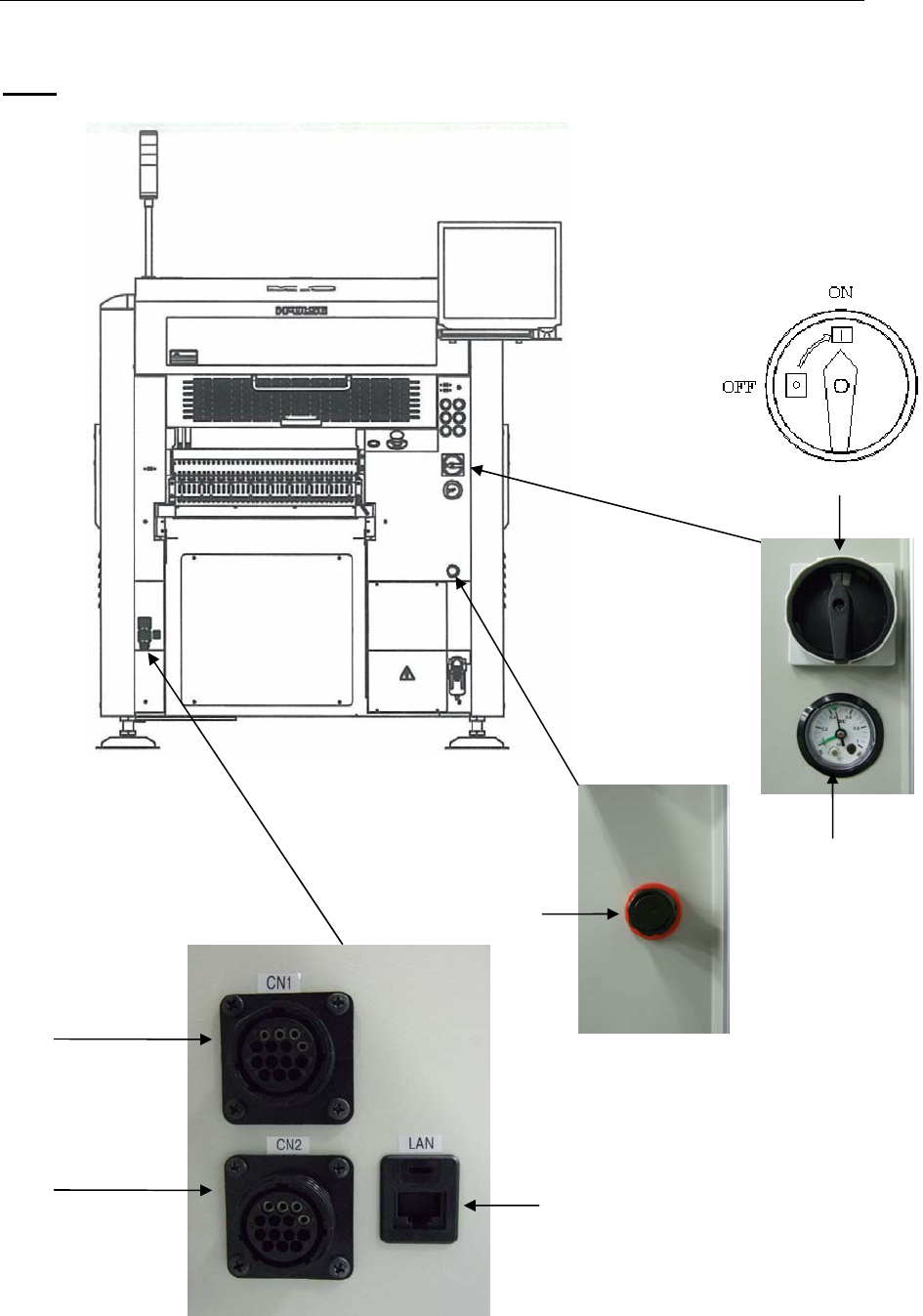
1-1-2 Connector Panel
M10
Front view
CN1
(Signal connector
for post-process)
CN2
(Signal connector
for pre-process)
Air regulator
1. Main Switch
Vacuum gauge
LAN port