M20_Ope_E - 第270页
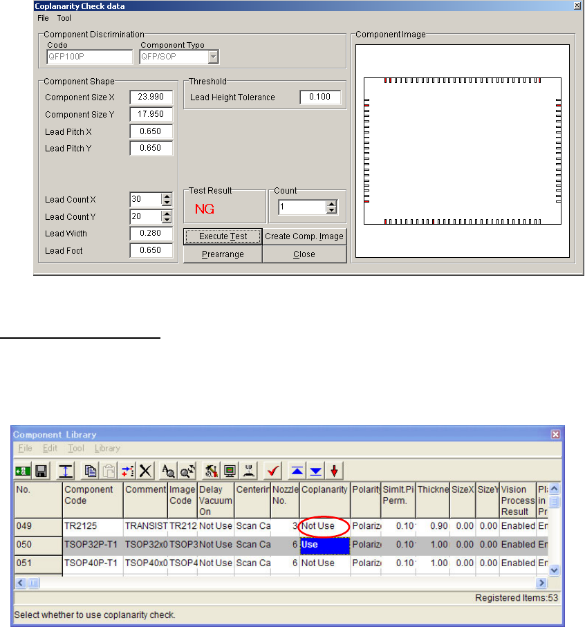
Chapter 6 Coplanarity Checker 6-10 5 The picture below shows NG status th at several Leads of QFP exceed the “ Lead Height tolerance ” . 6) Edit Component Library. After saving Coplanarity Check data, open Comp onent Lib…
Chapter 6 Coplanarity Checker
6-9
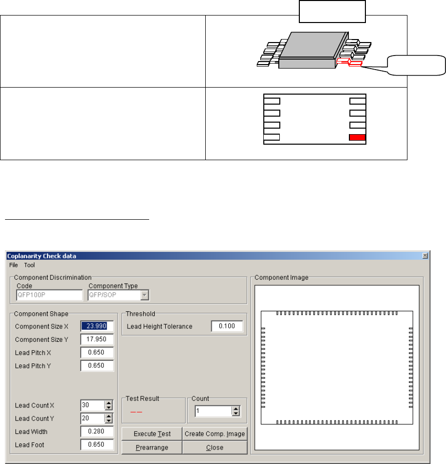
■Component Image
Component image is displayed in [Component Image] window in [Coplanarity
Check data] screen. In case leads are failed in Coplanarity Check test, they are
indicated in red color.
Component Packaging angle
(When facing to Mounter)
Component image
(in Coplanarity Check edit screen)
Note: The error leads are indicated in red color and the missing leads are indicated in light blue
color.
5) Execute Coplanarity Check test.
After all necessary items are entered, execute Coplanarity Check test as follows:
1 Click [Create Com. Image] button to display the component image.
The image is drawn by [Component Shape] data. Compare the image with the actual
component to check whether the [Component Shape] data are correct. (Component Size
X/Y is defined as outer length of Lead, and the Lead part is overlaid with the mold part in
the image drawing.)
2 Confirm the component is still attached to the nozzle since the step “2) Do Image Test”. If
the component is not attached, do the step “2) Do Image Test” again.
3 Click [Execute Test] button to do Coplanarity Check test.
4 In [Test Result] box, the result OK or NG is displayed. If the result is NG, check the error
status by a message and a [Component Image] display.
NG Lead
Ex.:SOP
Chapter 6 Coplanarity Checker
6-10
5 The picture below shows NG status that several Leads of QFP exceed the “Lead Height
tolerance”.
6) Edit Component Library.
After saving Coplanarity Check data, open Component Library screen to enable Coplanarity
Check function for the target Component code.
Set “Coplanarity” to [Use] in Component Library. (On the contrary, set it as [Not use] if
Coplanarity check is not needed for production.)
Note: If “Coplanarity ” function is set to [Use] for the Component Code without creating Image
Library, a Program Data Check error will occur.
①
Chapter 6 Coplanarity Checker
6-11
6-3 Maintenance
6-3-1 About Maintenance
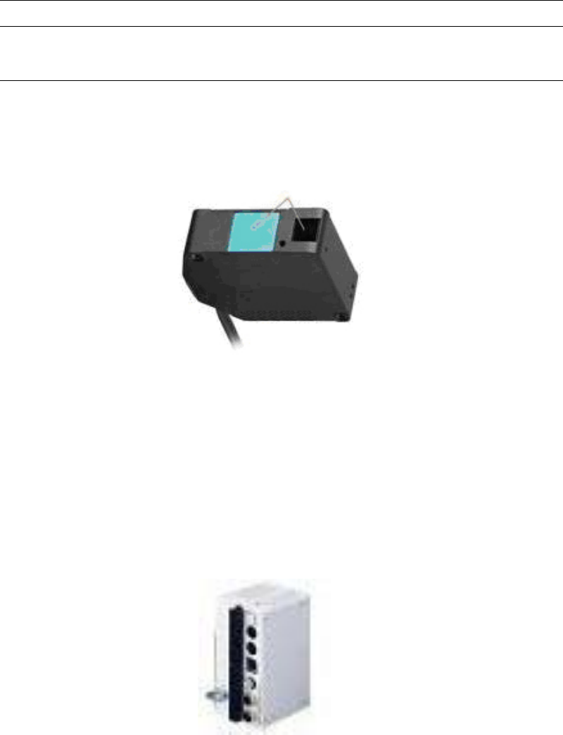
This chapter explains Daily Maintenance of the Laser sensor. In advance to start Maintenance
job, be sure to turn off the power of the Mounter to stop laser projection.
■Cleaning the surfaces of transmitting and receiving windows.
If oil, fingerprints, etc. are on the laser transmitting/receiving windows which may cause beam
refraction, or if dust or dirt which may cause beam blocking is on these windows, it may affect
the measurement accuracy. Clean the windows periodically.
• Blow off larger dust or dirt with a camera lens blower.
• Wipe off smaller dirt, fingerprints, etc. with a soft lens cleaning paper gently.
• For persistent dirt, wipe off carefully with a cleaning paper soaked by a little alcohol.
■Cleaning the controller
Wipe off adhered dirt from the controller with a clean and soft cloth gently.