M20_Ope_E - 第275页
Chapter 9 Running a Job 9-3 9-2 Pre-operation Check and Initial Setting 9-2-1 Summary The following lists what to check before a prog ram can be run. If you fail to check them, an error may result. Necessary data are e…
Chapter 9 Running a Job
9-2
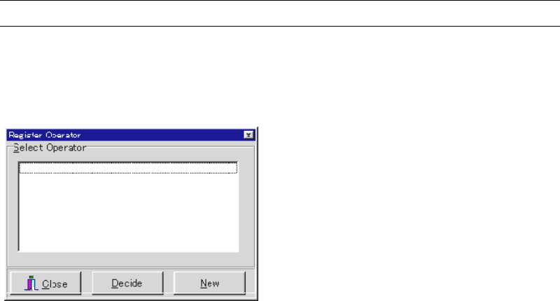
9-1 Registering the Operator
Menu: Management>RegisterOperator
Before executing job run, register the operator(s) here. The registered operator(s) will be
selectable for the Operator field in the Run dialog box.
Action:
① Click <New> button.
② The Operator Entry/Deletion dialog box appears. Under [Operator Entry] field, type an
operator name and click <Register> button. To register more than one operator, repeat
this step as necessary.
③ Click <X> button to close the dialog box.
④ Confirm that the registered operators are displayed in the Register Operator dialog box.
When you click an operator name and then click <Decide> button, it is displayed for the
Operator field in the Run dialog box by default. At the same time, it is entered to the
Operator field of Management>OperatorRecord as the next operator.
⑤ Click <Close> button to close the dialog box.
Chapter 9 Running a Job
9-3
9-2 Pre-operation Check and Initial Setting
9-2-1 Summary
The following lists what to check before a program can be run. If you fail to check them, an
error may result.
Necessary data are entered to Program> Board Data.
Required nozzles for the program have been set to the heads/ANC.
When using CTF-40, all the pallets are correctly stored in the stockers.
The feeder location conforms to the program.
9-2-2 Checking Board Data
Menu: Program> Board Data
Check mainly the following points:
Registration method (Edge/Pin) is correctly selected (Conveyor Speed, Registration).
The maximum component height to place and the maximum pre-processed component
height must be correctly entered (Max Pre-processed Component Height).
9-2-3 ANC Initial Setting
We recommend you to set all the required nozzles on ANC and remove unnecessary nozzles
from ANC and the heads beforehand.
Do not manually attach a nozzle to a head. Incomplete nozzle setting can result. In this case, the
head can hit other part of the mounter to cause machine damage.
However, you can remove a nozzle from a head manually.
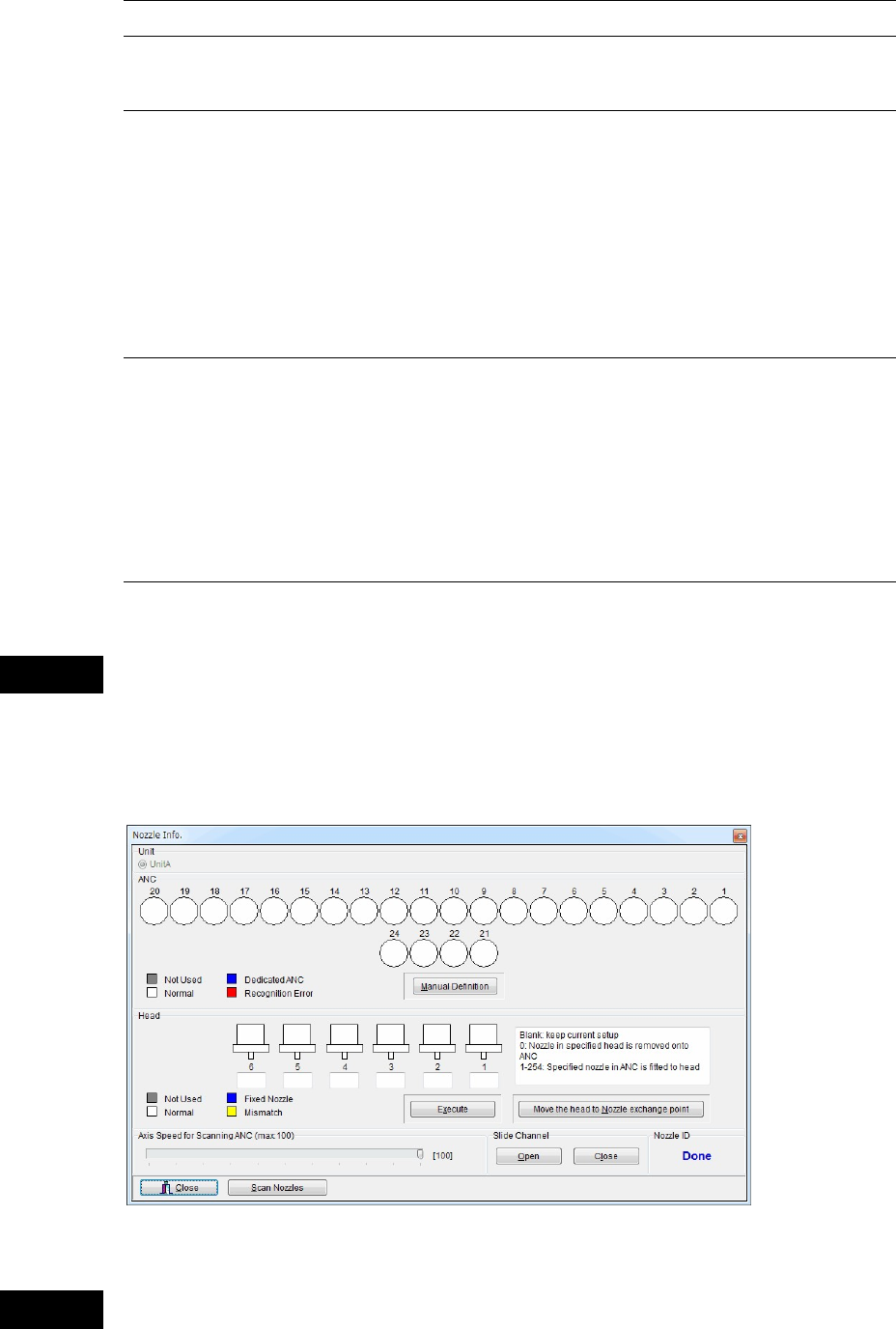
Menu: Manual>Nozzle Info.
Check the nozzle location in ANC and the heads. Relocate the nozzles if necessary.
ANC operation allows the head assembly to move. When executing this menu, do not
stick head, hands, or other parts of the body inside the mounter. Serious injury can
result. Also make sure non-operators are at a safe distance from the machine.
Caution
Warning
* The number of heads may vary
depending on the model.

Chapter 9 Running a Job
9-4
Automatic Nozzle ID Recognition
Click <Scan Nozzles> button. The multi scan camera scans each head for nozzle presence. Then
the main teach camera scans ANC to read the nozzle ID labels. When there is a nozzle/nozzles
in the head, they will be unloaded onto ANC. Then the main teach camera scans the placed
nozzle/nozzles for their ID labels.
The result is shown in [ANC] table. [Head] table is reset since no nozzle is in the head. [Nozzle
ID] field shows “Done” to indicate the process has been completed.
After executing automatic nozzle ID recognition, be sure to compare the
displayed result with the actual ANC setting if they match. Make sure in
particular that when a nozzle is present, the corresponding field of the ANC
table indicates as such (not blank).
When the nozzle ID label is stained with dirt, automatic nozzle ID recognition
may fail. In this case, wipe the nozzle ID label clean according to the
instruction in the Service Manual.
Manual Definition
If the automatic nozzle ID recognition fails, you can manually correct the nozzle Nos. In this
case click <Manual Definition> button to determine the change. Note that you cannot add or
subtract nozzles with this setting.
Note: In the nozzle library, the same kind of nozzle can have only a set of data.Relocating Nozzles
Nozzles can be exchanged between the specified heads and ANC.
To attach a nozzle to a head : Enter the corresponding “nozzle ID” into the box below the head
to which the nozzle is to be attached.
To remove the nozzle from a head : Enter “0” into the box below the head from which the
nozzle is to be removed.
When an entry is made for every head, click <Execute> to exchange the nozzles.
Setting the Axes Speed
Under [Axis Speed for Scanning ANC], specify the axes speed (X, Y, and Z) for nozzle
exchange.
Actuating the Slide Channel
Click <Open> button to open the ANC slide channel. Click <Close> button to close.
Note: On the M10 with 6 heads specification, there are unreachable ANC stations (detaching disabled
ANC stations) depending on the head to be used.
There is no limit of the M10 with 4 heads.
Mounter M10
Head Qty 4 6
Head No. 1 2 3 4 1 2 3 4 5 6
Unavailable ANC No. - - - - - - - -
1-2
9-10
17-18
1-4
9-12
17-20
Note: All the M20’s heads can reach any ANC stations.