M20_Ope_E - 第277页
Chapter 9 Running a Job 9-5 9-2-4 CTF-40 Initial Setting When a job run ended normally, all the pallets of CTF-40 are to be returned to their st ocker. Before running a job, make sure the status of each pallet in the fol…

Chapter 9 Running a Job
9-4
Automatic Nozzle ID Recognition
Click <Scan Nozzles> button. The multi scan camera scans each head for nozzle presence. Then
the main teach camera scans ANC to read the nozzle ID labels. When there is a nozzle/nozzles
in the head, they will be unloaded onto ANC. Then the main teach camera scans the placed
nozzle/nozzles for their ID labels.
The result is shown in [ANC] table. [Head] table is reset since no nozzle is in the head. [Nozzle
ID] field shows “Done” to indicate the process has been completed.
After executing automatic nozzle ID recognition, be sure to compare the
displayed result with the actual ANC setting if they match. Make sure in
particular that when a nozzle is present, the corresponding field of the ANC
table indicates as such (not blank).
When the nozzle ID label is stained with dirt, automatic nozzle ID recognition
may fail. In this case, wipe the nozzle ID label clean according to the
instruction in the Service Manual.
Manual Definition
If the automatic nozzle ID recognition fails, you can manually correct the nozzle Nos. In this
case click <Manual Definition> button to determine the change. Note that you cannot add or
subtract nozzles with this setting.
Note: In the nozzle library, the same kind of nozzle can have only a set of data.Relocating Nozzles
Nozzles can be exchanged between the specified heads and ANC.
To attach a nozzle to a head : Enter the corresponding “nozzle ID” into the box below the head
to which the nozzle is to be attached.
To remove the nozzle from a head : Enter “0” into the box below the head from which the
nozzle is to be removed.
When an entry is made for every head, click <Execute> to exchange the nozzles.
Setting the Axes Speed
Under [Axis Speed for Scanning ANC], specify the axes speed (X, Y, and Z) for nozzle
exchange.
Actuating the Slide Channel
Click <Open> button to open the ANC slide channel. Click <Close> button to close.
Note: On the M10 with 6 heads specification, there are unreachable ANC stations (detaching disabled
ANC stations) depending on the head to be used.
There is no limit of the M10 with 4 heads.
Mounter M10
Head Qty 4 6
Head No. 1 2 3 4 1 2 3 4 5 6
Unavailable ANC No. - - - - - - - -
1-2
9-10
17-18
1-4
9-12
17-20
Note: All the M20’s heads can reach any ANC stations.
Chapter 9 Running a Job
9-5
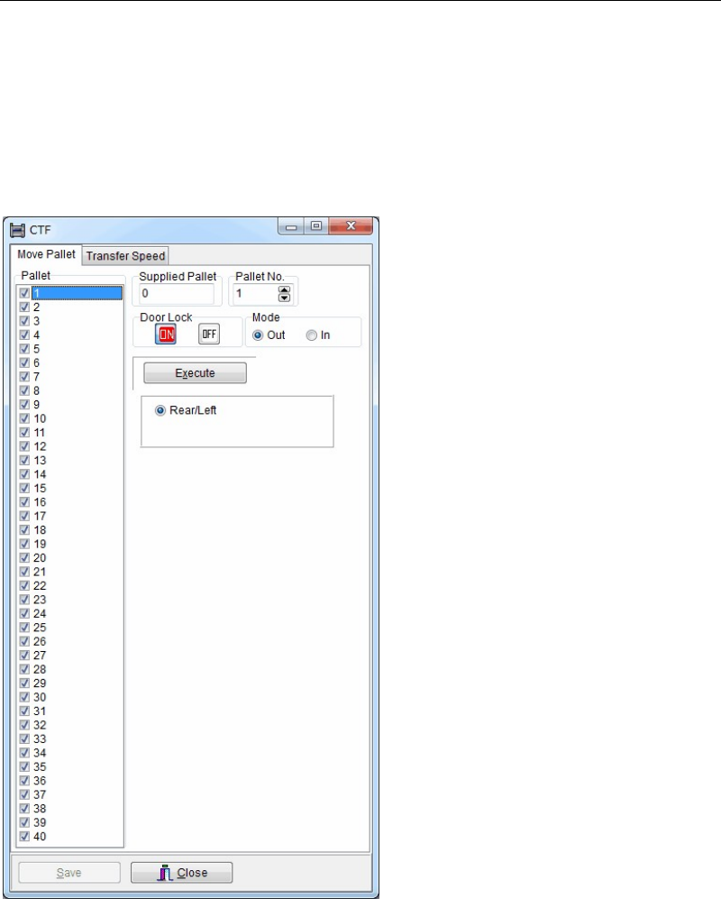
9-2-4 CTF-40 Initial Setting
When a job run ended normally, all the pallets of CTF-40 are to be returned to their stocker.
Before running a job, make sure the status of each pallet in the following window:
Menu: Run>Run>MX Info.
The pallet numbers from 1 to 40 are used for CTF-40.
When the pallet exists in the stocker, “o” is shown in [Status] field. In the latter case, access the
CTF dialog box.
Menu: Manual>CTF
Checked numbers indicate that the pallet is present in the stocker.
Action:
① Make all the axes return to their origins. (if necessary)
② Under [Pallet], specify an unchecked pallet.
③ Under [Mode], select <In> button.
④ Select <Execute> button which the specified pallet will return into the stocker.
⑤ Repeat ② through ④ for the remaining unchecked pallets.
Note: The [CTF] window can be opened by the operator, who is authorized to edit System Parameter
at Operator Management. If you are authorized to edit Pallet Library, you can move pallets in
the Pallet Library mode, instead of [CTF] menu. For details, see Chapter 5 Libraries > Pallet
Library.
Chapter 9 Running a Job
9-6
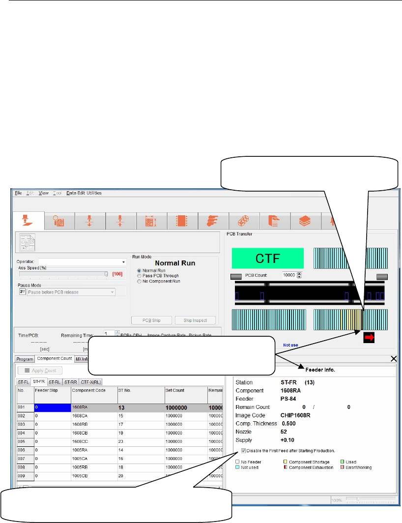
9-2-5 Confirming Feeder Setting
Menu: Run>Feeder Info
When selecting Run>Feeder Info, you can check that the feeder is set on the station specified by
the program in the [Feeder Info.] window. If a required feeder is not set, the corresponding
feeder station is displayed in brown. Conversely, when the feeder is set correctly, the
corresponding feeder station is displayed in yellow green. Note that this window indicates
only the presence/absence status of the feeders and does not check the feeder type. To check
the feeder type, you must visually check it.
Additionally, the feeder status, such as component shortage is also displayed in other color.
For details about indication colors, see the [feeder Info.] window.
Note: Install the feeder on the station properly.
If the feeder is lifted up from the proper position, the nozzle may collide with the feeder.
Note: When using this [Disable the First Feed after Starting Production] function, pay special
attention to the following points.
① When the data is updated, this setting is cleared. So, set this function during pause
immediately before starting the operation.
② This function is invalid for the MS-3 feeder.
③ Select User Parameter>Functions (1)> and check on [Disable the First Feed after Starting
production]. The first feed of all stations is not performed.
Ri
g
ht-clickin
g
a feeder position will
jump to the component pickup data
s
p
ecified for this ST number.
When the component is alread
y
present on the
feeder, check on this box to disable the first feed
after startin
g
p
roduction.
Left-clickin
g
a feeder position will displa
y
the [Feeder Info] window for this ST
number.