M20_Ope_E - 第280页
Chapter 9 Running a Job 9-8 Window: 1. Edit & Teach Used to edit the program during production. For details, see Edit & Teach Mode during a Job Run. 2. Operator: Select an operator name. Only operators registered…
Chapter 9 Running a Job
9-7
9-3 Running a Job
9-3-1 Running a Job
Executes actual continuous job run or test job run.
Before executing job run, check the machine setup according to Pre-operation Check and Initial
Setting in this Chapter.
Action:
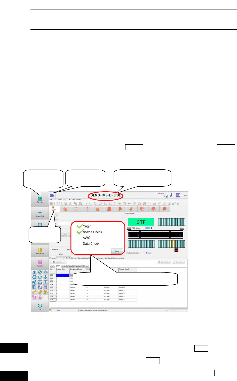
① Click the <Run> icon in the program area. The [Run] window appears.
② Click the <Open> icon. The [Select Program] window appears.
Select a program you want to run. The selected program name is displayed at the upper
part of the window.
③ In the main menu, click the <Run Now> icon. The mounter automatically performs the
following preparation tasks. The check mark is put after relevant task has been performed
completely.
z Origin
z Nozzle Check
z AWC
z Program Check
④ When all the tasks are performed, the
START switch starts blinking. Press the START
switch to start the job.
Note: Origin and Nozzle Check are already performed. These tasks are not performed unless they are
required.
Do not put your head or hand inside the mounter when pressing the Start switch.
Doing so may cause serious personal injury. Additionally, make sure that no one is
present around the mounter before pressing the Start
switch.
Do not place any foreign object inside the mounter or tray feeder when pressing the Start
switch. Doing so may cause the mounter or tray feeder to break.
①Click
[
Run
]
.
② Click
[
O
p
en
]
.
③ Click [Run
Now].
③ Check mark is put on prepared items.
② Program name is
dis
p
la
y
ed.
Warning
Caution
Chapter 9 Running a Job
9-8
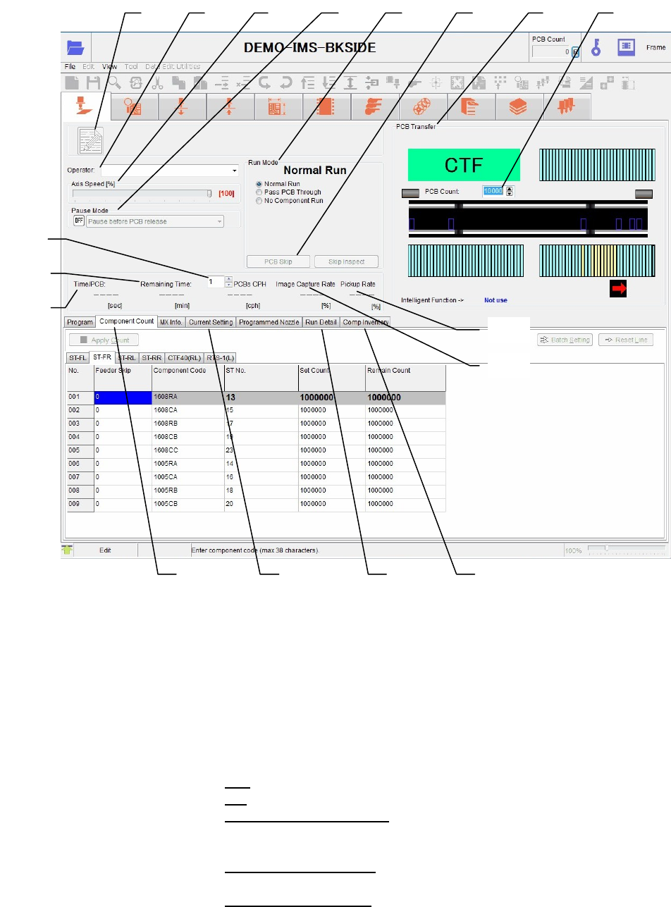
Window:
1. Edit & Teach Used to edit the program during production.
For details, see Edit & Teach Mode during a Job Run.
2. Operator: Select an operator name. Only operators registered for
Management>RegisterOperator are selectable here. Job run can be
performed without registering an operator.
3. Axis Speed [%]: Set a ratio to the maximum speed (100%) to slow down the speed of
all axes.
4. Pause Mode: You can pause a job run for every single PCB.
OFF
Job run continues without a pause.
ON
Select a desired pause method from the combo-box.
[Pause before PCB release]:
Job run pauses before a PCB is released (after production of one
PCB).
[Pause after PCB release]:
Job run pauses after a PCB is released (after production of one PCB).
[Pause before PCB load]:
Job run pauses without loading the next PCB after the current PCB
board has been unloaded.
1 2 3
4
5
7 6 8
9
10
11
12
13
17 14
15
16

Chapter 9 Running a Job
9-9
5. Run Mode: Normal:
Normal operation (Pick up → Vision process → Place) is performed.
Pass PCB Through:
PCB passes through without clamping the PCB or mounting
components.
No Component Run:
Vision processing is normally performed, but component on/off
check and offset compensation are not performed. Also pickup
vacuum check is not performed. So, the pickup retry does not occur.
No Feeding:
Feeder indexing is not performed for allowing non-component run.
No Comp. Countdown:
Component count is not checked. So, the component shortage does
not occur.
No PCB Change:
Program is repeated without changing the board. Deselecting this
option, the current board is unloaded. When the next board is
supplied, this board is loaded and the program is run.
Endless:
Regardless of PCB Count, no-component run continues endlessly.
Four options under <No Component> can be selected or deselected
during a non-component run.
6. PCB Skip When this button is executed in the [Cycle Stop] mode during
production, the mounting operation for the PCB will be stopped
immediately and the PCB will be transferred to the exit position.
(After the next PCB is loaded, normal production steps will be
performed.)
7. PCB Transfer: The PCB transfer status is displayed graphically. The input/output
status of the process signal is indicated by the lamps. When the
conveyor flow direction is left to right, the left side shows the
pre-process signal while the right side shows the post-process
signal.
Note: For 1-drive conveyor, pressing the arrow buttons at both ends of the
conveyor graphic can rotate the conveyor belt.
8. PCB Count: First, enter the number of PCBs to produce. Once the job run starts,
the display changes to show the number of produced PCBs
(Produced PCB count/Total PCB count). The PCB count increments
every time the PCB production is completed.
9. Time/PCB: Time required to manufacture a PCB.
10. Remaining Time: Remaining time until the current job run ends.
11. PCBs CPH: The number of components placed on the specified number of
boards per one hour.
12. Image Capture Rate The success rate of the component vision process is displayed.
13. Pickup Rate The success rate of the component pickup is displayed.
14. [Current Setting] tab: The current settings in the User Parameter are displayed.
Clicking the <Management Data> button will display the
Performance Record for the currently running program.
This data is the production management data when the button is
clicked. The data is not updated while the data is displayed.