M20_Ope_E - 第290页
Chapter 9 Running a Job 9-18 Run Mode Setting Menu: Run>Run>ComponentCount>ST-F/ST-R tab You cannot enter or change “ Set Count ” data. Because “ Set Count ” only shows the “ Initial Supply Count ” data. You c…
Chapter 9 Running a Job
9-17
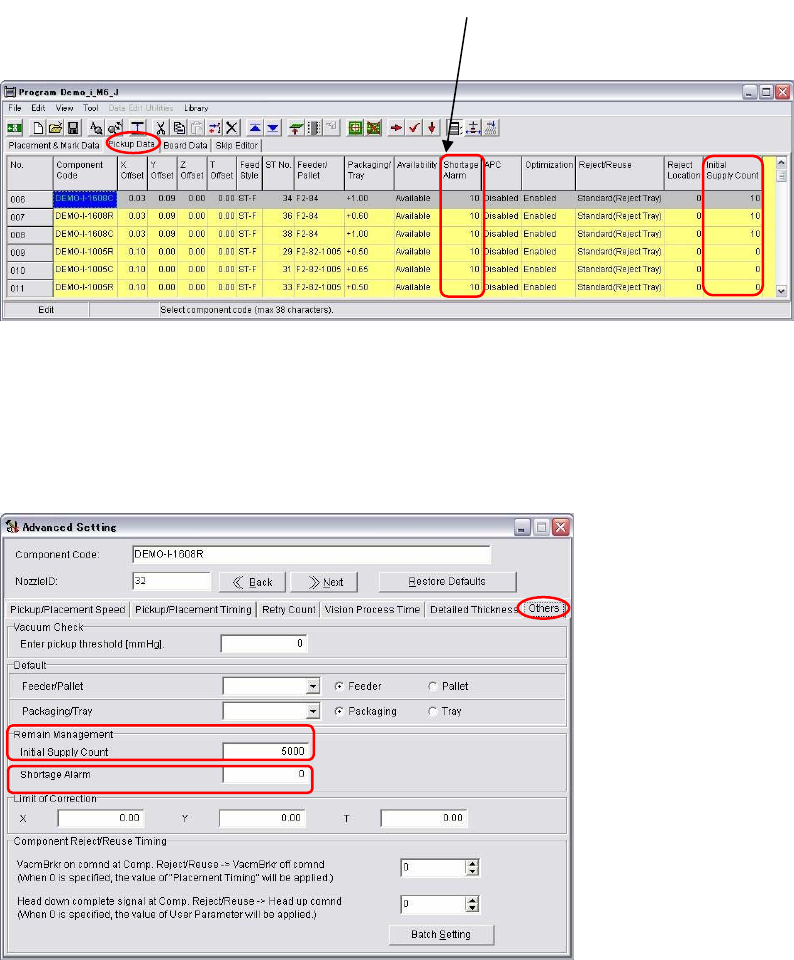
Pickup Data Setting
Menu: Program>PickupData
To manage component remain count by each feeder station, enter the number of components in
‘Initial Supply Count’ and “Shortage Alarm” in each pickup data.
Advanced Setting for Component Library
Menu: Library>ComponentLibrary>Tool>AdvancedSetting>Others
To manage remain components by each component library, enter in “Initial Supply Count” and
“Shortage Alarm” for [Remain Management].
Note:
There are three data to enter component-remain-count management. When you enter than
one data, only one data is used in the following priorities.
① Intelligent Server Data
② Pickup Data
③ Component Library
‘Shortage Alarm’ and ‘Initial
Supply count’ can be managed
by each pickup point.
Chapter 9 Running a Job
9-18
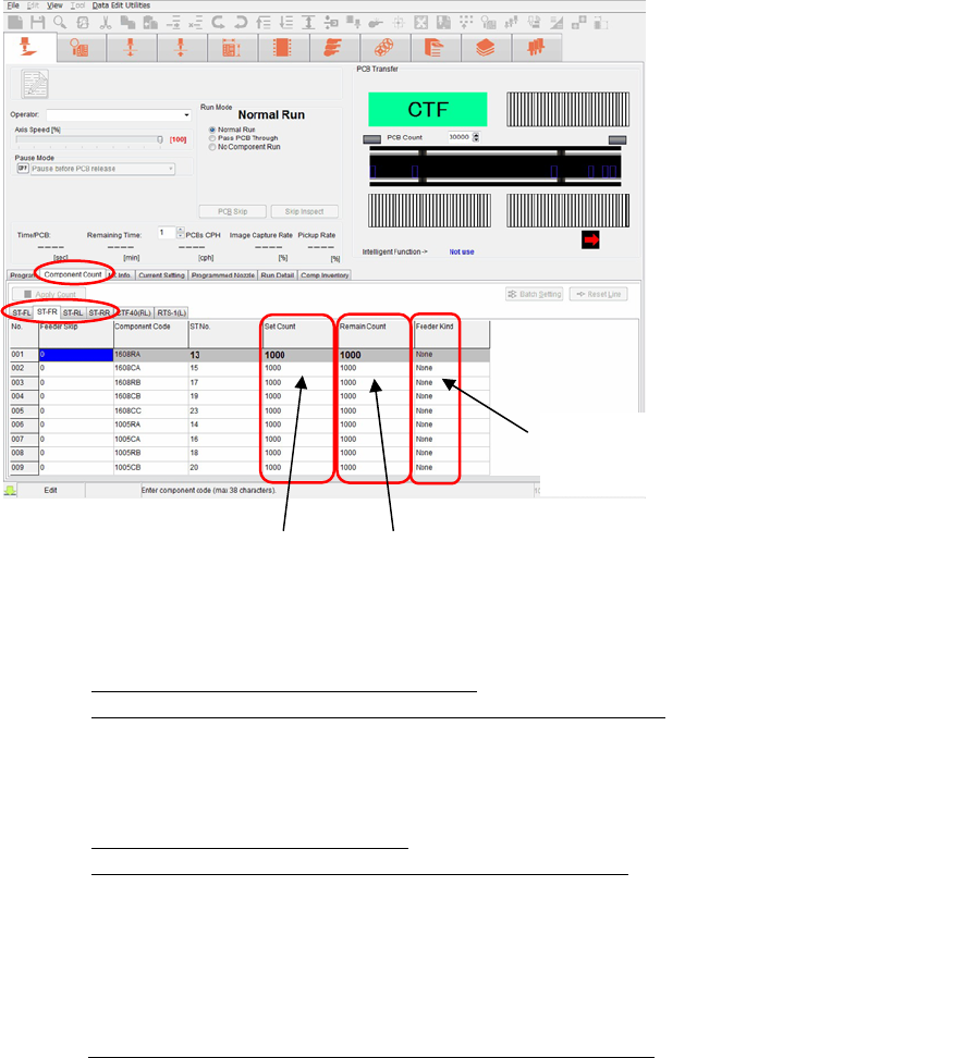
Run Mode Setting
Menu: Run>Run>ComponentCount>ST-F/ST-R tab
You cannot enter or change “Set Count” data. Because “Set Count” only shows the “Initial
Supply Count” data.
You can change “Remain Count”. When you changed it, press <Apply Count> to enter the
change. Be sure the priorities of component-remain-count management. (The order of priority
is; intelligent server, pickup data, and component library.) You can refer used feeders in
“Feeder Kind”.
■ How to use [Component Count]
Case1 : Component count management : Not use
Notice of component shortage and Component lack : Not use
Enter 0 in both [Initial Supply Count] and [Shortage Alarm] in Pickup Data and
component Advanced Setting window. Then 1,000,000 are entered in [Set Count] and
[Remain Count] in Run window automatically. Start the production.
Case 2: Managing component count : Use
Notice of Component shortage and component lack : Use
Enter the remaining number of components in [Initial Supply Count] and [Shortage
Alarm] in the component Advanced Setting window.
Enter 0 in [Initial Supply Count] and [Shortage Alarm] in Pickup Data to disable to
count with these columns. Then only the components in the component Advanced
Setting windows are counted.
Case 3: Same conditions as Case 2, but Packaging has been changed
Ex: This is the case that only packaging type is changed with the same components,
from reel to stick or to a large reel (15 inch reel).
In this case, leave the inputs unchanged in [Initial Supply Count] and [Shortage
Alarm] in the component Advanced Setting window as Case 2. Enter remaining
number of components of the replaced packaging in [Initial Supply Count] and
[Shortage Alarm] in Pickup Data. When remaining number of components are entered
both in Pickup Data and component Advanced Setting window, only the components
entered in Pickup Data are counted.
Data cannot be changed.
Data cannot be entered.
Data can be changed.
Data can be entered.
Intelligent Intelligent feeder
Normal
Feeder other than intelligent feeder
None No feeder
Chapter 9 Running a Job
9-19
9-3-3 Line Search (ASJ)
1
Menu: Program>Tool>Teach>Trace>SearchLine
Line search allows the driving axes to move. When performing line search, do not stick
head, hands, or other parts of the body inside the mounter. Serious injury can result.
Also make sure non-operators are at a safe distance from the machine.
Before starting line search, make sure no foreign obstacles are left in the mounter or tray feeder.
Otherwise, costly machine damage can occur.
Line search allows you to search for the program step line with the X,Y coordinates nearest from
the current head position.
During job run, by bringing the teach camera to the placement point whose coordinates setting
should be adjusted or checked and then executing line search, the program step line for the
placement point can be found.
Note: Line search requires the board size setting (X, Y) to be completed beforehand via Program>
Board Data>Coordinates>Board Size. The X or Y setting, whichever larger, is applied as the
search range for the main teach camera.
Action:
① Click Program>Tool>Teach to open the Teach dialog box.
② Under [Head], select “Main Teach Camera”.
③ Bring the main teach camera to the placement point.
④ In the Teach dialog box, under [Trace] tab, click <Search Line> button.
⑤ The program step line is found and highlighted.
9-3-4 Coplanarity Checker (optional)
To enable the Coplanarity Check Function, check [Coplanarity Check] box in System>User
Parameter>CoplanarityCheck.
For details, see Chapter 11 Parameter Setting.
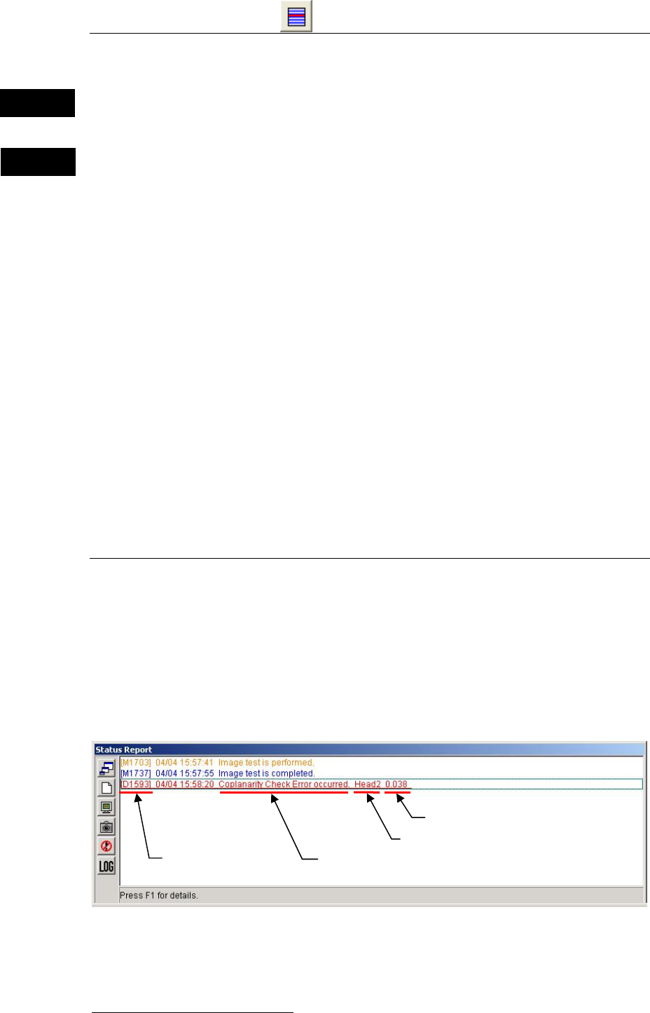
Error Messages
When an error occurs while coplanarity check or production is performed, the error
code/error message and the head No. appear by red color in [Status Report] window.
In this case, check the indicated cause of the indicated head.
1
ASJ: Automatic Search and Jump
Warning
Caution
Mounter error code
Head No.
Lead height shift
Mounter error message