M20_Ope_E - 第302页
Chapter 9 Running a Job 9-30 9-5-6 Image Data Re-edit The Image data re-edit function enables you to re-edit an image data of a failed component during a job run to place the same component on a PCB without rejecting nor…
Chapter 9 Running a Job
9-29
9-5-5-3 Edit & Teach during a Job Run (Tray Feeder)
Action:
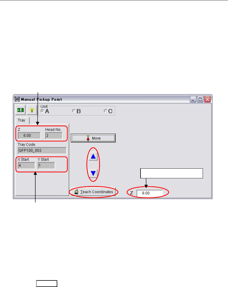
① When a pick up error happened on the tray feeder, a head travel confirmation message
appears. Click the <OK> button to move the same head to the tray pocket where the
pickup error happened.
② The following teach window appears. Teach the component surface with arrow keys.
Move the head down slowly by observing the clearance between the nozzle tip and the
component surface. While moving the head down, the head height coordinate is indicated
in the [Z] field.
Note: Do not move down the head quickly or the attached nozzle, the head, and the component may
cause damage. When the nozzle tip almost reaches the component surface, move down the
head approx. 1mm more for reliable pickup.
③ When the height is determined, click the <Teach Coordinates> button.
④ The procedures hereafter is same as for ST-F/ST-R described in the prior section.
Change the component height in the tray data and save the change.
⑤ Press the START
switch to restart the job run.
Note: If still pickup error happens, try to lower the component height approx. 0.1mm more.
Component height entered in the tray data and
the head No. which had
p
icku
p
error a
pp
ears.
The position of tray pocket where
the pickup error happened.
Head height coordinate
Chapter 9 Running a Job
9-30
9-5-6 Image Data Re-edit
The Image data re-edit function enables you to re-edit an image data of a failed component
during a job run to place the same component on a PCB without rejecting nor putting back in
the original tray pocket.
Setting
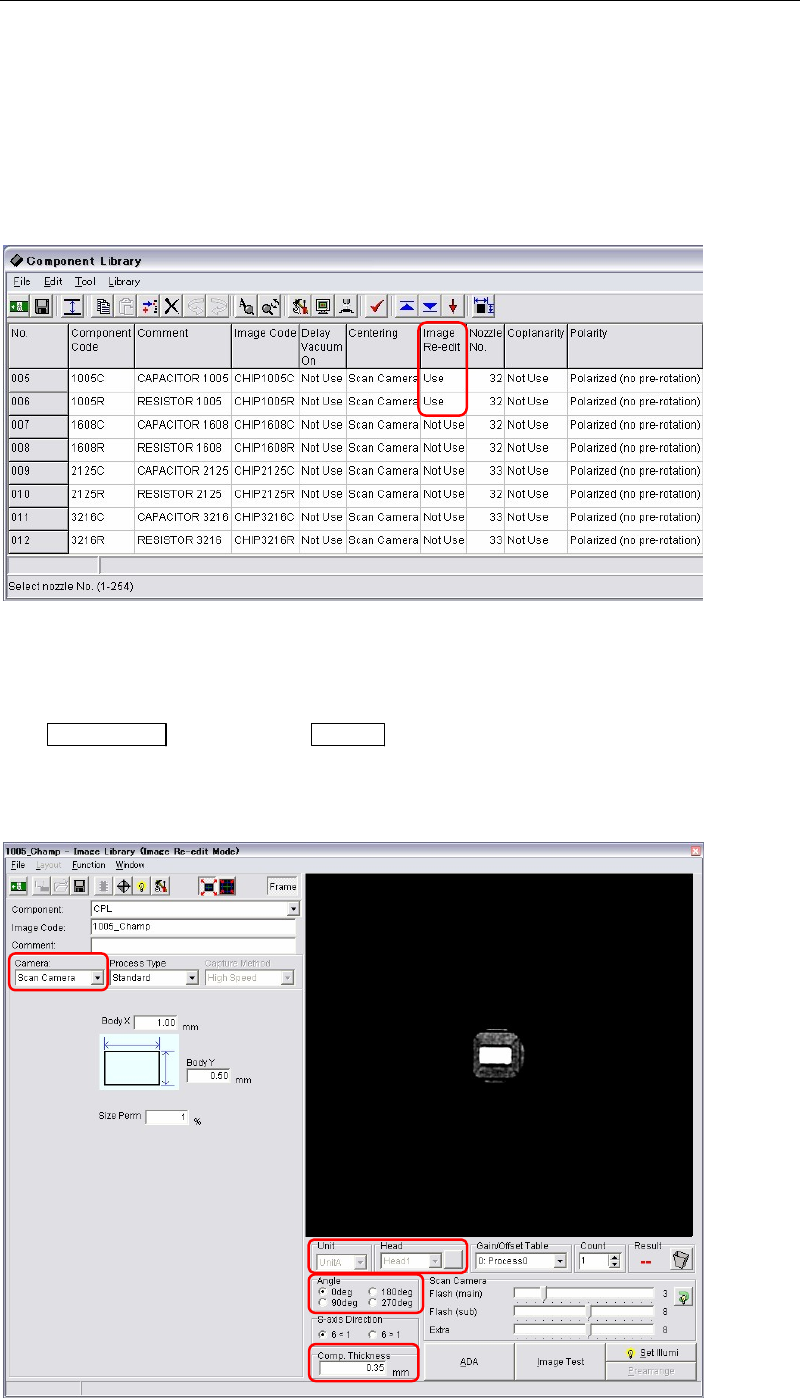
Menu: Library > Component Library
Action: Choose “Use” in the [Image Re-edit] column for the components you want to use this function.
Operating the image data re-edit
Action:
① If the mounter stops due to image capture error during a job run, first press the
ALARM OFF
switch (and the CLEAR switch) to stop the alarm.
② The image edit window (image data re-edit mode) appears. At this time the component
which image capture error occurred is still picked up by a nozzle without rejecting nor
putting back in the tray pocket.
Chapter 9 Running a Job
9-31
③ The necessary items, [Camera], [Head], [Comp. Thickness] etc., are already entered. Just
modify the necessary data. Also the ADA is available.
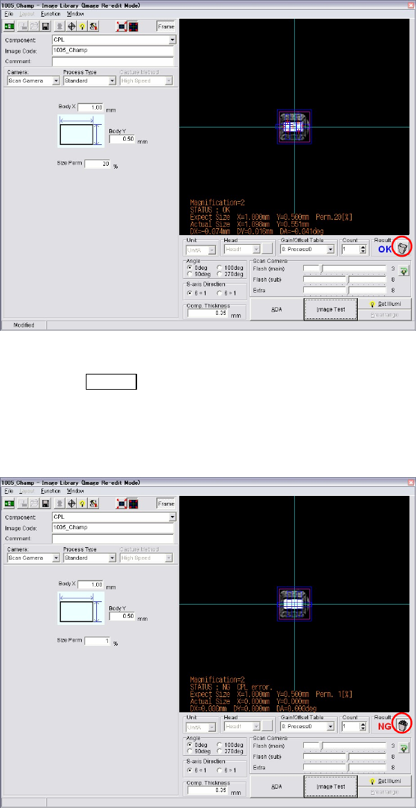
④ When the image data re-edit is complete, execute image test.
⑤ When the result is “OK”, the trash box next to the result is empty. It means the component
is no need to be rejected or put back to the tray.
⑥ Save the image data. Close the image data edit window.
⑦ Press the START
switch to restart the job run.
The component still picked up is image captured and placed on a PCB with the newly
captured image. The re-edited image data is used for the placement hereafter.
⑧ If the picked up component is a defective, image test will fail as “NG”. In this case, click
the trash box to make it full. Restart a job run. The component will be rejected or put back
to a tray, and retry a pickup for the next component.
Note: Clicking the trash box changes the box status, full and empty.
z Empty trash box : When the trash box is empty, you can re-edit the component
currently picked up and can use the component for placement.
z Full trash box : When the tray box is full, the component currently picked up will be
rejected or put back on a tray. And the next component will be picked up for a retry.