M20_Ope_E - 第317页
Chapter 10 Replenishing Com ponents and Using Maintenance Menus 10-13 10-4 Signal I/O Signal I/O stands for signal input/output. Signal input refers to an input signal sent from each sensor. Signal output refers to an ou…
Chapter 10 Replenishing Components and Using Maintenance Menus
10-12
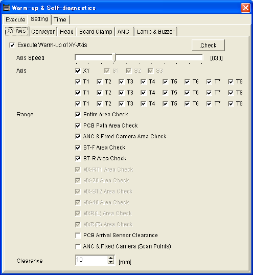
Setting tab
Open each tab (XY-axes, Conveyor, Head...) and specify items to be warmed up in detail. To
warm up only the items specified in a single tab, check the top check box in the tab and click
<Execute> button.
Use [Actuator Clearance] as default setting.
Time tab
Specify interval between executions of warm-up operation. At a system startup at which the
specified interval has passed since the last warm-up, the system asks you whether to execute
warm-up. Setting increment is hour.
Note: When you enter “0” for the warm-up interval, the system won’t ask you for confirmation on
whether to execute warm-up.
* The number of heads, number of Z
axes, and number of θ axes differ
depending on the mounter model.
Chapter 10 Replenishing Components and Using Maintenance Menus
10-13
10-4 Signal I/O
Signal I/O stands for signal input/output. Signal input refers to an input signal sent from each
sensor. Signal output refers to an output command sent to each actuator.
The Signal Output (Control) window serves as controls to move actuators for checking their
movements. In response to their movements, the Signal Input (Monitor) window shows the
positions of motors and actuators and the sensor On/Off status.
10-4-1 Signal Input Monitor
You can check the current status (On/Off) of each sensor. “1” indicates on, “0” off. When a
sensor detects the movement of a switch, motor, or actuator, the Signal Input Monitor shows the
sensor status change. This is also used to find a wire disconnection or sensor failure.
Menu: Menu: Manual>Signal I/O>Signal Input (Monitor)
■ List ………. Not used
■ Details…… Not used
■ FIO……….. Not used
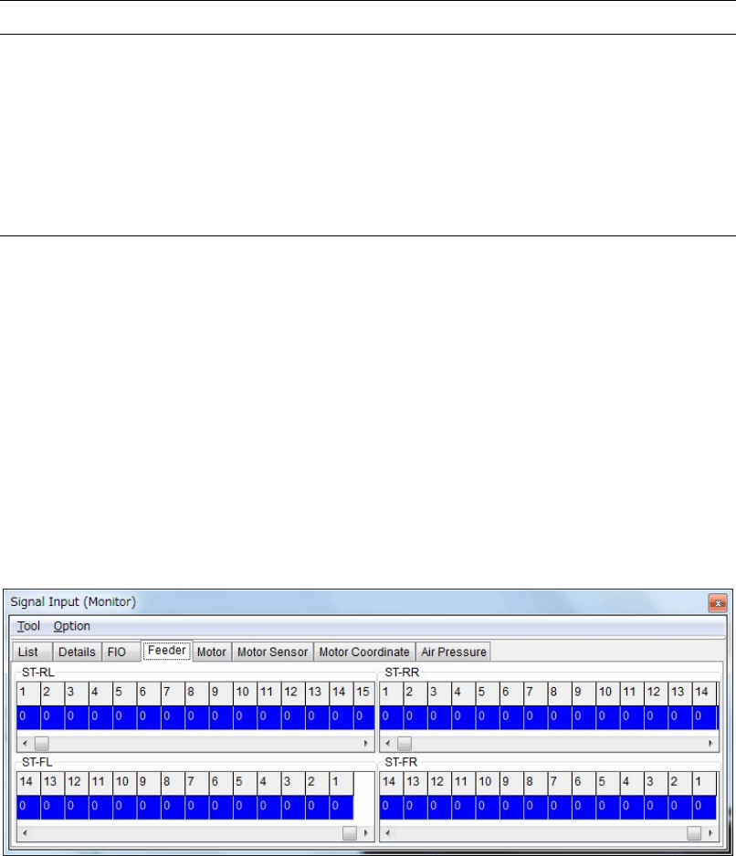
■ Feeder
“1” indicates no feeder is set.
“0” indicates a feeder is set.
The upper part is the signal input monitor for the front feeder bank.
The lower part is the signal input monitor for the rear feeder bank.
Chapter 10 Replenishing Components and Using Maintenance Menus
10-14
■ Motor
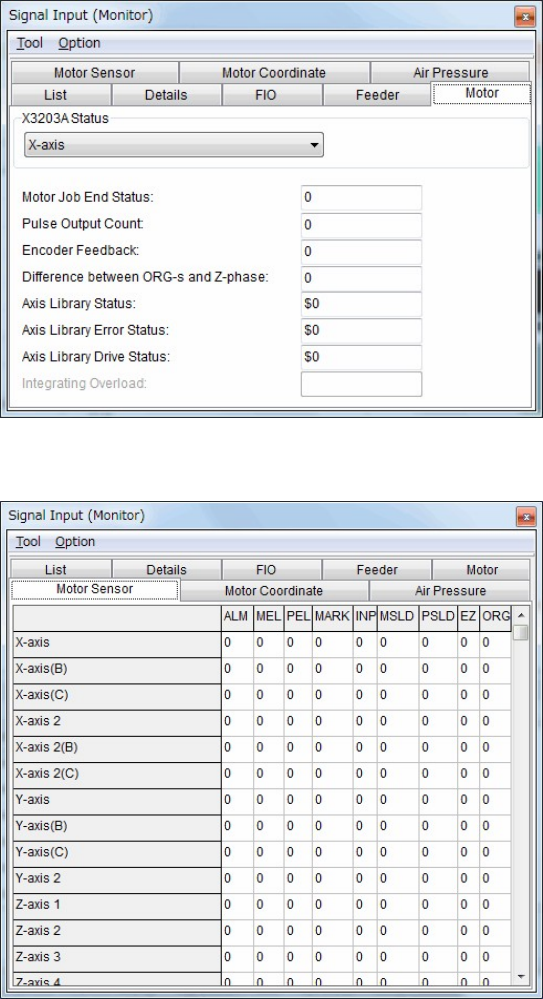
■ Motor sensor
Window:
ALM: Alarm
MEL: Minus End Limited
PEL: Plus End Limited
MARK: Mark
INP: In Position
MSLD: Minus Slow Down
PSLD: Plus Slow Down
EZ: 0 Phase
ORG: Origin