M20_Ope_E - 第32页
Chapter 1 General 1-14 1-1-3 Alarm Beacon (option) Alerts the operator to vari ous machine states visually. Machine State Beacon State Beep (High-pitched tone) Green Yellow Red White* Run Running Lights Pausing Lights Er…
Chapter 1 General
1-13
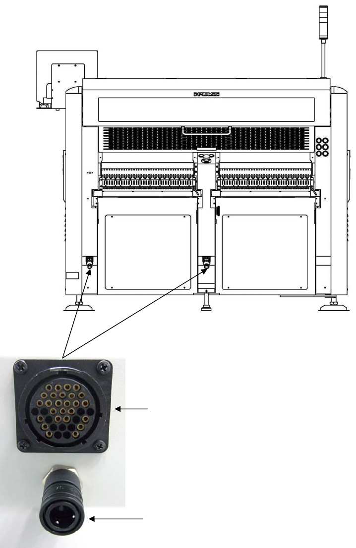
Connector for CTF-40
Signal & Power
Air socket for CTF-40
Rear view
Note: When using the CFB-36 instead of using the CTF-40 on the rear of the mounter, plug the shorting
connector into the “Connector for CTF-40 Signal & Power.”
Chapter 1 General
1-14
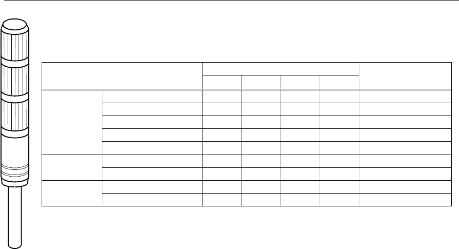
1-1-3 Alarm Beacon (option)
Alerts the operator to various machine states visually.
Machine State Beacon State Beep
(High-pitched tone)
Green
Yellow
Red White*
Run Running Lights
Pausing Lights
Error Blinks
continuous
Out of component Blinks
intermittent
Component shortage
Lights
Blinks
Manual
/Teach
Normal Lights
Error Lights
Blinks
continuous
Others
(Pause)
Normal Lights
Error Blinks
Lights continuous
* The white light is optionally available.
* Alarm beacon status for component exhaustion/shortage can be changed in User Parameter.
Chapter 1 General
1-15
1-2 System Startup and Shutdown
1-2-1 System Startup
Note: Before turning ON the power, check that no USB memory is inserted into the USB port. If a USB memory
is inserted, be sure to remove it and then turn ON the power.
Action:
① Turn the MAIN
switch 90 degrees clockwise to turn ON the power
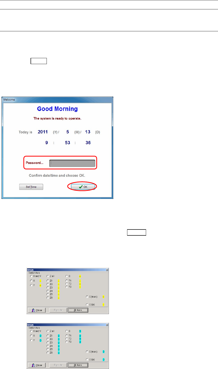
② After a short time, the following window appears, check the date and time. If they are correct, type
the password (given by the administrator) and click <OK> button. Even if no password is typed,
you can still proceed by clicking <OK> button. (The next step will automatically start if no entry is
made for about 30 seconds after the window appears.)
③ Windows and the MMI system start automatically, and a window indicating that the system is
starting up appears. Wait for a while.
④ The main menu appears in the screen.
⑤ Wait for approximately five seconds and then press the READY
switch to turn on the servo
motors.
⑥ Take the machine origin. Select Manual>Origin and click the <All Axes> button.
When the symbols next to the axis names change from yellow “-“ to blue “O”, origins of all the axes
are taken.
Before the axes origins are initialized
After the axes origins are initialized