M20_Ope_E - 第325页
Chapter 10 Replenishing Com ponents and Using Maintenance Menus 10-21 Manual Action: ① Click <OFF> buttons to move PCB Stopper up and set PCB Clamp. The buttons will be turned to <ON>. ② Click <ON> bu…
Chapter 10 Replenishing Components and Using Maintenance Menus
10-20
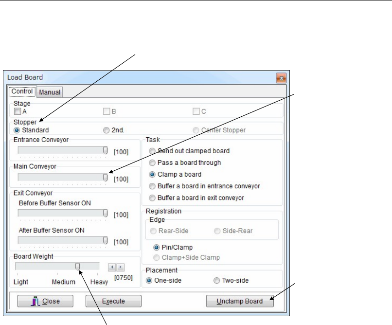
10-4-6 Load Board
Menu: Manual>Load Board
Runs the conveyor to load or unload a board.
Control
Two-side Placement
When <One-side> is specified under [Placement], the loaded board starts to exit the mounter as
soon as the board is unclamped. When <Two-side> is specified, the loaded board starts to exit
the mounter after the board is unclamped and also the support pins (adjust plate) are
completely lowered.
Be sure to specify <Two-side> when the board has pre-processed components at its bottom.
This prevents interference between the components and the support pins.
Loading and Clamping a Board
Action:
① Place a board at the conveyor entrance where the beam of the entrance sensor is blocked.
② Select the stopper to use.
③ Under [Registration], select a registration method.
④ Select [Placement].
⑤ Click <Execute> button. The conveyor starts to run, and a board is loaded and clamped in
place.
Task Setting
Send out clamped board: Unloads a board set in the processing position.
Pass a board through: Passes a board through without clamping it in the processing
position.
Clamp a board: Loads and then clamps a board in the processing position.
Buffer a board in entrance...: Holds a board standby on the entrance conveyor.
Buffer a board in exit...: Holds a board standby on the exit conveyor.
Adjust the each conveyor
speed.
Select the sto
pp
er to use
Clicking this button unclamps
the board.
If the board is too heavy to reach the stopper, move this slider to the right.
Chapter 10 Replenishing Components and Using Maintenance Menus
10-21
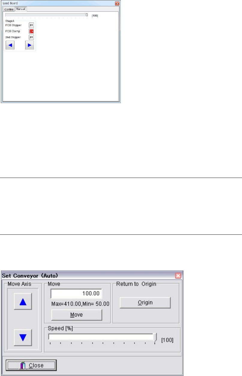
Manual
Action:
① Click <OFF> buttons to move PCB Stopper up and set PCB Clamp. The buttons will be
turned to <ON>.
② Click <ON> buttons to move PCB Stopper down and release PCB clamp. The buttons will
be turned to <OFF>.
③ Click Arrow buttons to rotate the conveyors.
10-4-7 PCB Sensors
Menu: Manual>PCB Sensors
Allows you to view the PCB sensor status graphically. When a PCB sensor responds, the
corresponding portion of the graphic turns yellow.
10-4-8 Conveyor Width
Menu: Manual>Set Conveyor (Auto)
This menu is used for the automatic conveyor width adjuster, and also for moving the conveyor
width in jog mode and returning the conveyor axis to its origin.
Window:
Move Axis: Hold down an arrow button with the mouse to move the adjustable
conveyor rail. [Axis Speed] is adjustable (10-100%) only after the
conveyor axis has returned to its origin.
Chapter 10 Replenishing Components and Using Maintenance Menus
10-22
Return to Origin: Click <Origin> button to make the conveyor axis return to its origin.
For safety consideration, the conveyor once widens itself for about
20mm and then moves to the origin. After the origin acquisition,
<AWC> button on the Status Display will be enclosed by square
brackets (AWC turns to [AWC].).
Move: Click <Move> after entering a width. The conveyor is first widened
40mm more than the width you entered and then adjusted to the
width you entered.
Note: The Set Conveyor (Auto) dialog box is also accessible via Program>File>BoardData. See
Chapter 2, Annotating and Editing Board Data for information.
Before changing the conveyor width, make sure all push-up pins are removed.
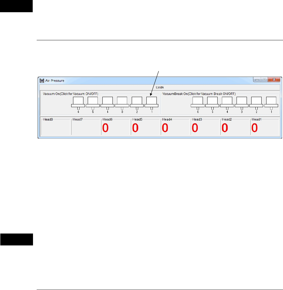
10-4-9 Air Pressure
Menu: Manual>Air Pressure
* The number of heads differs depending on the mounter model.
Window:
z Vacuum On
Click (check) a desired head and the head starts vacuuming. Click the head again (uncheck) and
the head stops vacuuming.
z VacuumBreak On
Click (check) a desired head and the head starts vacuum-breaking. Click the head again
(uncheck) and the head stops vacuum-breaking.
Before performing vacuum-breaking, make sure that the nozzle is removed from the head.
Performing vacuum-breaking with the nozzle attached may cause the nozzle to pop out from
the head. (This especially happens with small-bore nozzles.)
10-4-10 Nozzle Info.
Menu: Manual>Nozzle Info.
See ANC Initial Setting in Chapter 9.
Caution
Caution
Head mark