M20_Ope_E - 第350页
Chapter 11 Parameter Setting 11-4 11-1-3 Head Escape Menu: System>UserParameter>HeadEscape When necessary, set the head parking coordina tes for the following conditions; component shortage, component remaining err…
Chapter 11 Parameter Setting
11-3
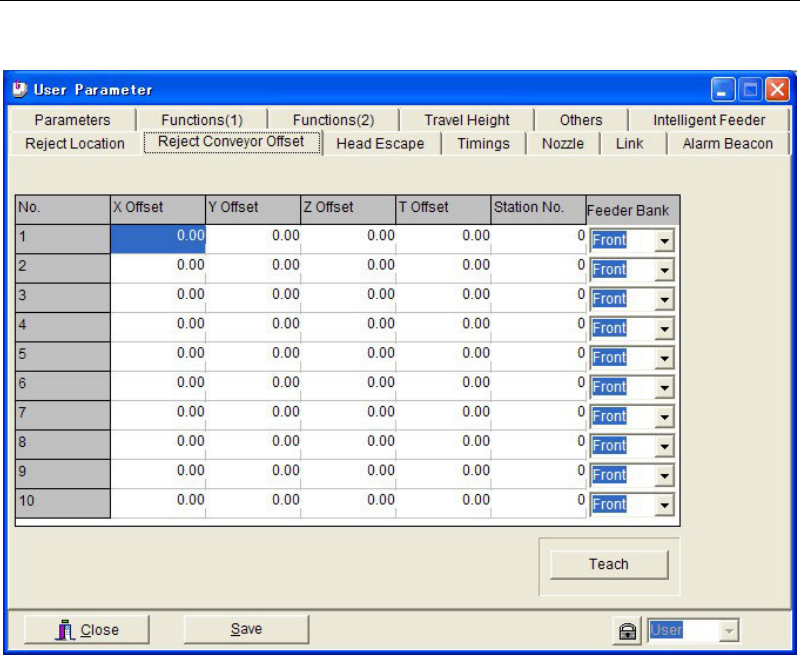
11-1-2 Reject Conveyor Offset
Menu: System>UserParameter>RejectConveyorOffset
Set coordinate offsets for the component reject location on the reject conveyor. When using the
specified reject location (pickup coordinates of the station where the reject conveyor is
connected), the offset setting here is not necessary.
Up to 10 coordinate offsets can be registered. [Reject Location] setting in the pickup data is
associated to the data number (No. 1–10) in this tab when [Reject/Reuse] is set to “Reject
Location”.
Note: For information on how to use the reject conveyor, see the instruction manual for the reject
conveyor.
Chapter 11 Parameter Setting
11-4
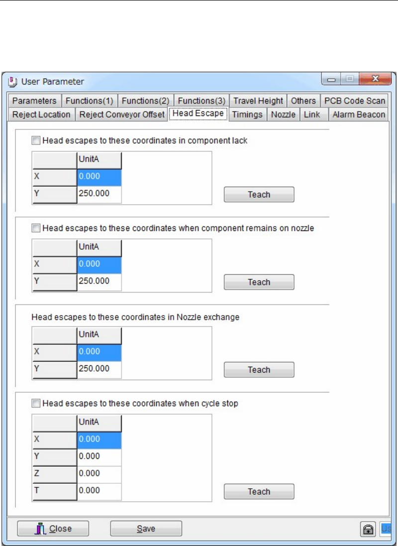
11-1-3 Head Escape
Menu: System>UserParameter>HeadEscape
When necessary, set the head parking coordinates for the following conditions; component
shortage, component remaining error, during nozzle exchange, and during cycle stop. Usually
use the initial parking coordinates.
Action:
① Click a <Teach> button to open the teach window. Teach and enter the desired escape
coordinates.
② When the check boxes of [Head escapes to these coordinates in component lack], [Head
escapes these coordinates when component remains on nozzle], and [Head escapes to
these coordinates when cycle stop] are clicked, the entered escape coordinates in this
window are used.
When these boxes are not checked, the escape coordinates of [Head Parking] in Program >
Board Data are used for unchecked items.
Chapter 11 Parameter Setting
11-5
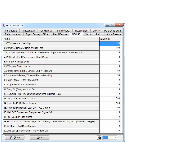
11-1-4 Timings
Menu: System>UserParameter>Timings
Set the sequence timings. Use the default setting normally.
Window:
1. XY Stop --> Mark Sensing
2. Conveyor Transfer Time at Error Stop
3. XY Stop for First Placement --> XY Move for Compensated Placement Position
4. XY Stop for First Placement --> Head Down
5. XY Stop --> Image Scan
6. XY Stop --> Detect Nozzle
7. Component Reject, Z Lowest End --> Head Up
8. Component Reuse, Z Lowest End --> Head Up
9. S-axis Stops --> Start Placement
10. Z Upper End --> S-axis Moves
11. Delay for [Delay Vacuum On]
12. Conveyor Run Time after Transfer Time in Board Data
13. Delay for PCB Simul. Transfer
14. Timer for PCB Clamp Timing
15. Timer for Placement Start after PCB Clamp
16. Wait PCB Entrance -> Pre-process Signal Off
17. PCB Vacuum Break Time
18. Pre-transfer at clamp down (2-side-board)(0:Down sensor ON, 100:Up sensor OFF) [%]
19. XY Stop -> Bad Mark Sensing
20. Grid-Lok up Command -> Placement Start
Note: Unit: ms