M20_Ope_E - 第352页
Chapter 11 Parameter Setting 11-6 11-1-5 Link Menu: System>User Parameter>Link ■ Enable link between ST-F and ST-R If this checkbox is checked, the link between the front and rear feeder banks is enabled. ● [Pickup…
Chapter 11 Parameter Setting
11-5
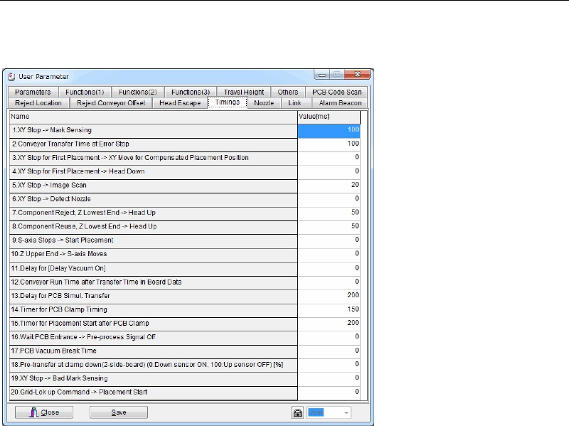
11-1-4 Timings
Menu: System>UserParameter>Timings
Set the sequence timings. Use the default setting normally.
Window:
1. XY Stop --> Mark Sensing
2. Conveyor Transfer Time at Error Stop
3. XY Stop for First Placement --> XY Move for Compensated Placement Position
4. XY Stop for First Placement --> Head Down
5. XY Stop --> Image Scan
6. XY Stop --> Detect Nozzle
7. Component Reject, Z Lowest End --> Head Up
8. Component Reuse, Z Lowest End --> Head Up
9. S-axis Stops --> Start Placement
10. Z Upper End --> S-axis Moves
11. Delay for [Delay Vacuum On]
12. Conveyor Run Time after Transfer Time in Board Data
13. Delay for PCB Simul. Transfer
14. Timer for PCB Clamp Timing
15. Timer for Placement Start after PCB Clamp
16. Wait PCB Entrance -> Pre-process Signal Off
17. PCB Vacuum Break Time
18. Pre-transfer at clamp down (2-side-board)(0:Down sensor ON, 100:Up sensor OFF) [%]
19. XY Stop -> Bad Mark Sensing
20. Grid-Lok up Command -> Placement Start
Note: Unit: ms
Chapter 11 Parameter Setting
11-6
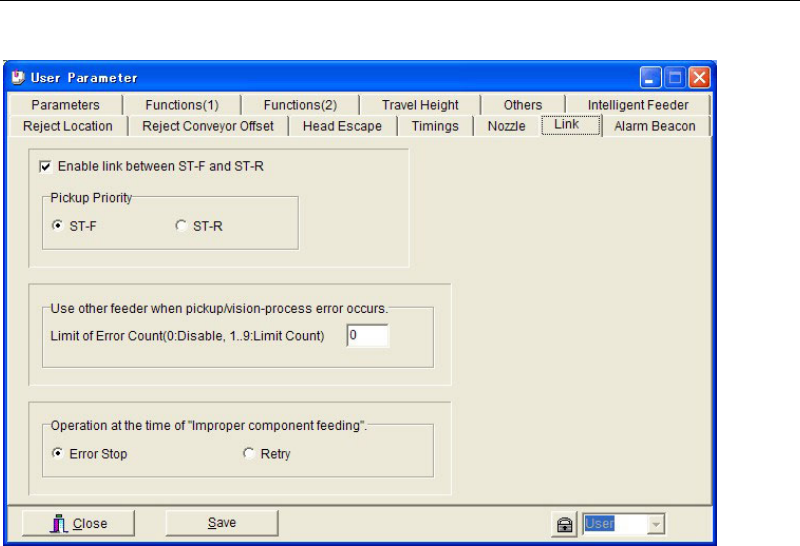
11-1-5 Link
Menu: System>User Parameter>Link
■ Enable link between ST-F and ST-R
If this checkbox is checked, the link between the front and rear feeder banks is enabled.
● [Pickup Priority]
Specify the feeder bank that is to be used with priority. If components of the same code are
present on both front and rear feeder banks, select “ST-F” to give priority to the front feeder
bank, or select “ST-R” to give priority to the rear feeder bank.
■ Use other feeder when pickup/vision-process error occurs
[Limit of Error Count (0: Disable, 1…9: Limit Count)]
If pickup/vision-process error occurs continuously with the same feeder, the pickup point is
automatically shifted (linked) to another feeder to which the same component code is
registered.
If pickup/vision-process error occurs continuously with the same feeder and the error count
reaches “Limit of Error Count”, the mounter cancels use of that feeder and instead uses another
linked feeder (i.e. a feeder to which the same component code has been registered).
“1” will be set in [Feeder Skip] in [ST-F]/[ST-R] tab page (Run > Component Count).
Note: This function is enabled by entering a value (1 to 9) in [Limit of Error Count].
● [Feeder Skip]
“0” in [Feeder Skip] in [ST-F]/[ST-R] tab page (Run > Component Count) indicates that the
feeder is usable, and “1” indicates that the feeder is not usable. A setting can also be made
manually in [Feeder Skip].
■ Operation at the Time of "Improper Component Feeding”
Used to specify how the mounter should operate in case of improper component feeding (e.g.
feeder hardware trouble).
When “Error Stop” is selected, the mounter will stop if an improper component feeding error
occurs. In this case, an error message “D1310 Improper component feeding” will be displayed.
(Note: “D1310” is used for automatic logging)
When “Retry” is selected, normal retry will be performed (i.e. retry is performed until the
“Choke”/”Feeder Retry” (Component Library > Advance Setting) or “Limit of Error Count” is
reached). In this case, an error message “D1599 Improper component feeding” will be
displayed.
Chapter 11 Parameter Setting
11-7
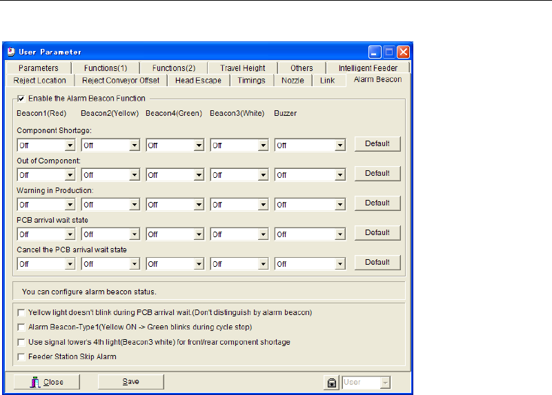
11-1-6 Alarm Beacon
Menu: System>UserParameter>AlarmBeacon
You can modify the alarm beacon status for notifying component shortage or exhaustion. The
saved setting is enabled only after you restart the system.
■ Yellow light doesn’t blink during PCB arrival wait (Don’t distinguish by alarm beacon)
■ Alarm Beacon-Type1 (Yellow ON -> Green blinks during cycle stop)
■ Use signal tower’s 4
th
light (Beacon3 white) for front/rear component shortage
■ Feeder Station Skip Alarm