M20_Ope_E - 第367页
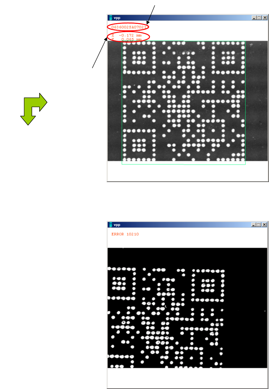
Chapter 11 Parameter Setting 11-21 ■ Code recognition Recognized code can be checked on the sc reen by clicking <Image Test> button. Good result image (OK) Bad result image (NG) Recognized code The amount of deviat…
Chapter 11 Parameter Setting
11-20
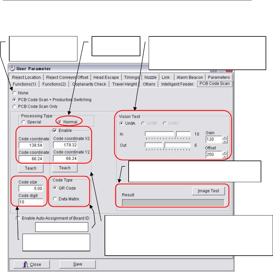
11-1-13 PCB Code Scan (Optional)
Menu: System>UserParameter>PCB_CodeScan
Note: To use a barcode as Board ID, input the scan point of barcode and the scan brightness.
When PCB is loaded and clamped at the mount stage, PCB Code Scan is performed at the Code
coordinates with the illuminations entered in User Parameter.
When “PCB Code Scan + Production Switching” box is selected, PCB Code is scanned before
starting the production and production will switch to the scanned program automatically.
★ Maximum registry number : 5000 records
“Code digit” is the numbers of characters used as a program name quoted from PCB Code. The
numbers of characters are counted from the beginning of the PCB code string.
Example: When PCB Code contains “abcdefg12345” and “10” is entered in “Code digit”, the program
name will be “abcdefg123”.
Note: When a PCB code includes such unacceptable characters as listed below in its string, only
alphanumeric characters (letters or digits, or both) that are located right before the unacceptable
character are used as a program name.
¥ / : , ; * ? " < > |
★Maximum : 38 characters long
Note: Click <Teach> to input Code coordinates by teaching.
- Board Code size [mm]
- Code digit
Select Code type.
X and Y coordinates of PCB Code from the machine origin
(stopper position). [mm]
If PCB Code scan fails at the ‘standard coordinates’ (left
input) , Code coordinates (X2,Y2) are enabled and the scan
will be performed again at the Code coordinates (X2,Y2).
Illumination settings for Teach camera used to
scan PCB Code.
For more details, see Chapter 5 Libraries,
Illumination Settings.
Check Normal for
Processing Type.
Select whether to perform
PCB Code Scan and/o
r
Production Switching or not.
Board Code scan test
Click <Image Test> to perform Image Test of Board
Code. The scanned Board Code is displayed in “Result”.
Chapter 11 Parameter Setting
11-21
■Code recognition
Recognized code can be checked on the screen by clicking <Image Test> button.
Good result image (OK)
Bad result image (NG)
Recognized code
The amount of deviation from
the programmed Code
coordinates.
(with reference to upper left)
X
(
+
)
Y
(
+
)

Chapter 11 Parameter Setting
11-22
■Switch the production program manually
When following error occurs at switching the program automatically, an operator can switch
the program manually.
A) PCB code could not be recognized.
B) The production program corresponding to the recognized PCB code did not exist.
C) The production program corresponding to the transferred program name did not exist.
When the error A) , B) or C) above occurs, Select Program window automatically appears to
select the process from three choices below.
① Highlight the program and click <Select> button to select it.
② Click <Continue> button to continue the current production.
③ Click <X> or <Close> button to close the Select Program window. If the PCB code could
not be recognized resulting in an error, PCB code will be recognized again at restarting the
production.
Executing any process from ① to ③ above recovers from an error. Push
START switch to
restart the production.
Note: An error occurred at switching the program cannot be released by
RECOVERY switch.
Perform any process mentioned above.
■Timing of transferring the information between machines
In upstream, the machine will output the information to the downstream machine when the
current machine starts unloading a PCB. In downstream, the machine will input the transferred
information *at the completion of PCB loading.
*The completion of PCB loading for the machine with buffer stopper is when a PCB is detected
by the buffer sensor, and for the machine without buffer stopper is when a PCB is clamped at
the main clamp.
Select Program window
Button to determine
the program
Button to continue
the current program
When closing the Select Program
window with either button, PCB
code will be recognized again.
PCB code recognition error