M20_Ope_E - 第40页
Chapter 1 General 1-22 1-3-3 Program Data Mapping Placement & Ma rk Data Code ( compon ent ) ( mark ) Reference Designator Comment X / Y / Z / T Head F Group No. B Group No. T ask Data Type Skip Picku p Data Componen…
Chapter 1 General
1-21
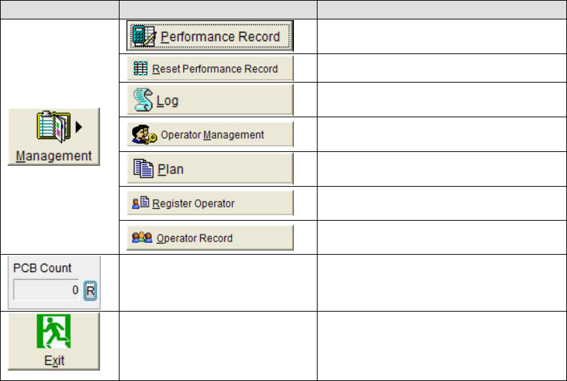
Main menu bar Sub-menu
Displays and outputs performance
records.
Reset performance record.
Displays recorded events that occurred
during the machine operation.
Allows registering access level and
password of various operator levels.
Allows registering a program to run.
Allows registering/deleting Operator’s
name.
Displays Start/End time of each job by
each operator’s name.
Displays the production PCB count from
previous counter reset to present. Clicking
the <R> button will reset the counter.
Shuts down system.
Note: The display of the command related to the option function may vary depending on the option installation
status.
Chapter 1 General
1-22
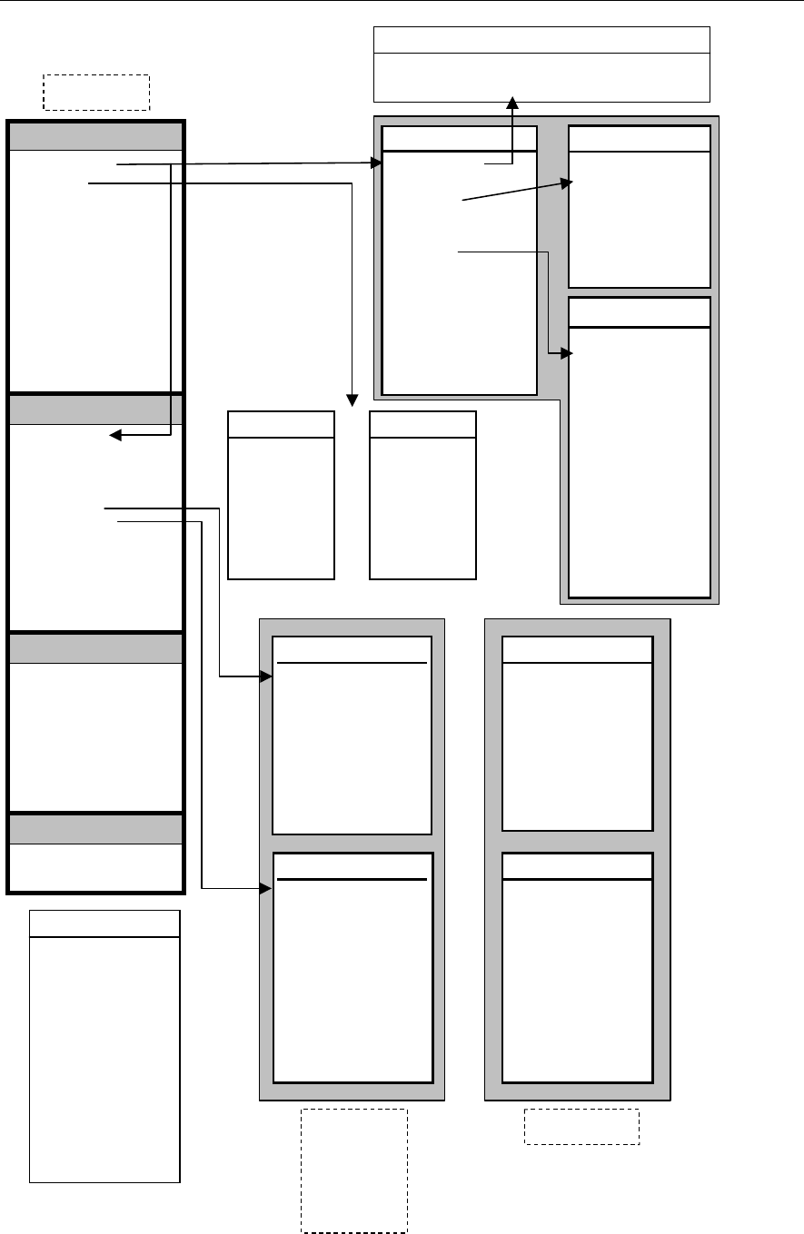
1-3-3 Program Data Mapping
Placement & Mark Data
Code
(
component
)
(
mark
)
Reference Designator
Comment
X / Y / Z / T
Head
F Group No.
B Group No.
Task
Data Type
Skip
Pickup Data
Component Code
X / Y/ Z / T Offset
Feed Style
ST No.
Feeder / Pallet
Packaging / Tray
Availability
Shortage Alarm
APC
Optimization
Reject / Reuse
Reject Location
Board Data
Mount Stage Count (For M7)
Coordinates (Board Origin)
(Board Size)
(Head Parking)
Transfer Speed
Head Travel Height
Transfer Conditions
Others
Header
Comment
Editor
Component Library
Component Code
Comment
Image Code
Delay Vacuum On
Centering
Nozzle No.
Coplanarity
Polarity
Simlt. Pickup Perm.
Thickness
Size X/Y
Vision Process Result
Placement in Scan Process
Optimization Priority
Image Library
Component
Image Code
Comment
Camera
Multi Views
Size Settings
Illumination, etc.
Nozzle Library
Nozzle
Nozzle No.
Choke Threshold
Pick Threshold
Directionality
Inner Diameter
Vacuum Check
Special Nozzle
Delay for Grip ON
Grip Length
Side Pickup Offset
Comp. Remain Check
ANC ID
Remain Check Code
Place Correct Table
Fiducial Data
Algorithm
Mark Code
Comment
Mark X / Y
Distance X / Y
Match. Threshold
Search Area
Mark Shape
Bad Mark Data
Image Type
Mark Code
Comment
Brightness
Search Area X
Search Area Y
Or
Feeder Library
Feeder
Feeder Code
Feed Pitch
Feed Height
X Offset
Y Offset
Practicable Pickup Range XY
Width from Pickup Point to
the left/right end
Pallet Library
Pallet
Feed Style
Pattern
Pallet No. 1
X Offset 1
Speed
Y Offset 1
Pallet No. 2
X Offset 2
Or
Packaging Library
Packaging
Pitch
Height
Package Angle
Tray Library
Tray
Pitch X / Y
Count X / Y
Original X / Y
Component Height
Package Angle
Postpone Retry
Or
for
Tape Feeders
Stick Feeders
Bulk Feeders
for Tray Feeders
User Parameter
Reject Location
Reject Conveyor Offset
Head Escape
Calibration
Timings
Nozzle
Alternate
Alarm Beacon
Parameters
Functions(1)
Funtions(2)
Coplanarity Check
Fixed Nozzle Info.
Program
A
dvanced Setting
Pickup / Placement Speed, Pickup / Placement Timing, Retry
Count, Vision Process Time, Detailed Thickness, Others

Chapter 1 General
1-23
1-4 Movable Range of Head Assembly
■ The following describes unavailable feeder stations of each head (feeder stations containing
unreachable pickup points).
Mounter M10
Head Qty 4 6
Head No. 1 2 3 4 1 2 3 4 5 6
Unavailable ST
No. (F)
34-36 36
- -
32-36 34-36 36
- - -
Unavailable ST
No. (R)
1-3 1 1-5 1-3 1
Mounter M20
Head Qty 4 6
Head No. 1 2 3 4 1 2 3 4 5 6
Unavailable ST
No. (FL)
34-36 36
- -
30-36 32-36 34-36 36 - -
Unavailable ST
No. (FR)
- - - - 1 1-3 1-5 1-7
Unavailable ST
No. (RL)
1-3 1 1-7 1-5 1-3 1 - -
Unavailable ST
No. (RR)
- - - - 36 34-36 32-36 30-36