M20_Ope_E - 第474页
Chapter 16 Dispenser 16-4 16-1-2 Setting the PCB data This data sets the PCB data's [PCB Warp Check by Laser]. Menu : PCB data: 2 Random setting If an [Action] ② Laser PCB warpage measurement step has been created…
Chapter 16 Dispenser
16-3
Note: The creation of this [Action] ② Laser PCB warpage measurement step is not required when [PCB data: 2]
> [PCB Warp Check by Laser] > [Check Method] > [Dispensing] > [Auto Check] (explained later in this
manual) is selected.
③ Next, create a dot station step.
In this step, the test dispense is performed on the paper sheet on the dot station and this is captured
by the teach camera to automatically adjust the dispense diameter to the set diameter (dispense
area).
In [Code], select [Dispense code] that is created with the dispense data described later. In the [X], [Y],
[Z], and [θ] cells, leave the value “0”.
In [Head], select a head, on which the dispense head is installed. Select “Dot station” in [Task].
Note: When [Eject time after a pause] and [Eject dot count after a pause] of the syringe data described later are
set, the pre-dispense can be performed on the dot station after paused for several seconds and the
pre-dispense onto the PCB is not needed.
④ Next, create a PCB dispense step.
In [Code], select [Dispense code] that is created with the dispense data described later.
In [X] and [Y], enter coordinates of the dispense point on the PCB.
In [Head], select a head, on which the dispense head is installed. Select “Dispense” in [Task].
Note: Multiple dispense point offsets from [X] and [Y] of the above reference dispense point on the PCB can be
set with the dispense data described later.
⑤ Next, create a component placement step when necessary.
Note, however, that component placement is not possible with the D10 dispenser.
Chapter 16 Dispenser
16-4
16-1-2 Setting the PCB data
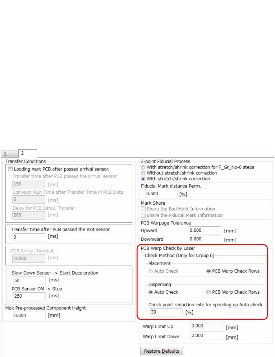
This data sets the PCB data's [PCB Warp Check by Laser].
Menu: PCB data: 2
Random setting
If an [Action] ② Laser PCB warpage measurement step has been created at the Placement & mark
(program) shown above, click the following item to enter a check-mark: [PCB data: 2] > [PCB Warp Check
by Laser] > [Check Method] > [Dispensing] > [PCB Warp Check Row].
Laser measurement then occurs at the created laser PCB warpage measurement step.
Auto setting
If the [PCB data: 2] > [PCB Warp Check by Laser] > [Check Method] > [Dispensing] > [Auto Check] was
selected (check-mark entered), a dispense point laser measurement will occur.
Therefore it is not necessary to create an [Action] ② Laser PCB warpage measurement step in the
Placement & mark (program). This simplifies the Placement & mark (program).
Moreover, when this [Auto Check] is specified, the number of measurement points gradually decreases
at the [Check point reduction rate for speeding up Auto check] item, with the final result being as follows:
[All dispense points] x [Check point reduction rate for speeding up Auto check].
Use the default setting for the [Check point reduction rate for speeding up Auto check] function.
Chapter 16 Dispenser
16-5
16-1-3 Dot station setting
Set the position where the dot station is installed.
Note, however, that this setting is not required for the D10 dispenser.
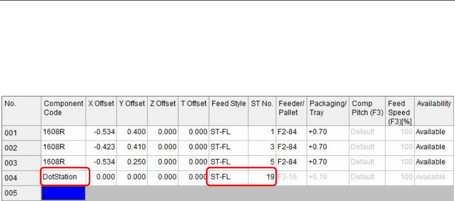
Menu: Pickup Data
Action:
① Install the dot station on the feeder bank.
② In [Component Code] of [Pickup data], enter “DotStation”.
③ In [Feed Style], select a feeder bank on which the dot station is installed.
④ Enter [ST No.] on which the dot station is installed.
Note: “DotStation” to be entered in [Component Code] is a specific code.
Carefully check upper and lower case characters when entering “DotStation”.
When you have entered this “DotStation”, cells other than [Feed Style] and [ST No.] become invalid.