M20_Ope_E - 第475页
Chapter 16 Dispenser 16-5 16-1-3 Dot station setting Set the position where the dot station is installed. Note, however, that this setting is not required for the D10 dispenser. Menu : Pickup Data Action: ① Install the d…
Chapter 16 Dispenser
16-4
16-1-2 Setting the PCB data
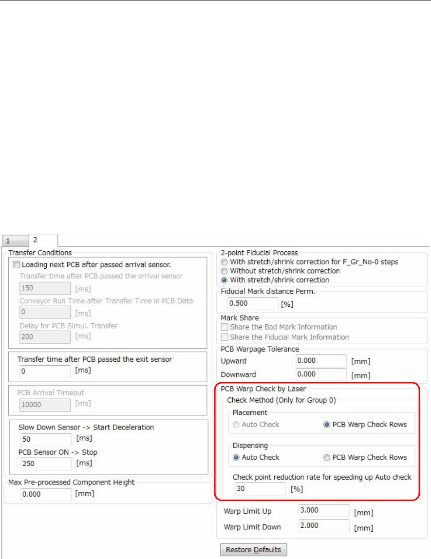
This data sets the PCB data's [PCB Warp Check by Laser].
Menu: PCB data: 2
Random setting
If an [Action] ② Laser PCB warpage measurement step has been created at the Placement & mark
(program) shown above, click the following item to enter a check-mark: [PCB data: 2] > [PCB Warp Check
by Laser] > [Check Method] > [Dispensing] > [PCB Warp Check Row].
Laser measurement then occurs at the created laser PCB warpage measurement step.
Auto setting
If the [PCB data: 2] > [PCB Warp Check by Laser] > [Check Method] > [Dispensing] > [Auto Check] was
selected (check-mark entered), a dispense point laser measurement will occur.
Therefore it is not necessary to create an [Action] ② Laser PCB warpage measurement step in the
Placement & mark (program). This simplifies the Placement & mark (program).
Moreover, when this [Auto Check] is specified, the number of measurement points gradually decreases
at the [Check point reduction rate for speeding up Auto check] item, with the final result being as follows:
[All dispense points] x [Check point reduction rate for speeding up Auto check].
Use the default setting for the [Check point reduction rate for speeding up Auto check] function.
Chapter 16 Dispenser
16-5
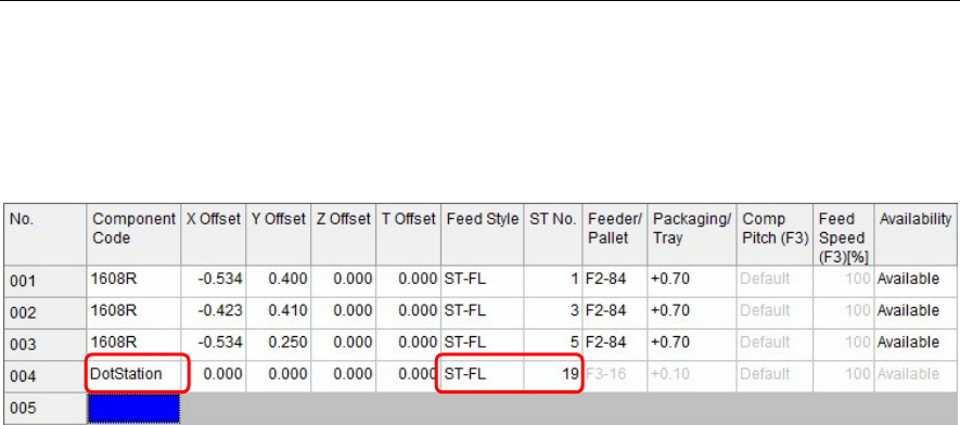
16-1-3 Dot station setting
Set the position where the dot station is installed.
Note, however, that this setting is not required for the D10 dispenser.
Menu: Pickup Data
Action:
① Install the dot station on the feeder bank.
② In [Component Code] of [Pickup data], enter “DotStation”.
③ In [Feed Style], select a feeder bank on which the dot station is installed.
④ Enter [ST No.] on which the dot station is installed.
Note: “DotStation” to be entered in [Component Code] is a specific code.
Carefully check upper and lower case characters when entering “DotStation”.
When you have entered this “DotStation”, cells other than [Feed Style] and [ST No.] become invalid.
Chapter 16 Dispenser
16-6
16-1-3-1 Dispenser related data
This dispense related data includes dispense data, syringe data, and dispense nozzle data as described
below.
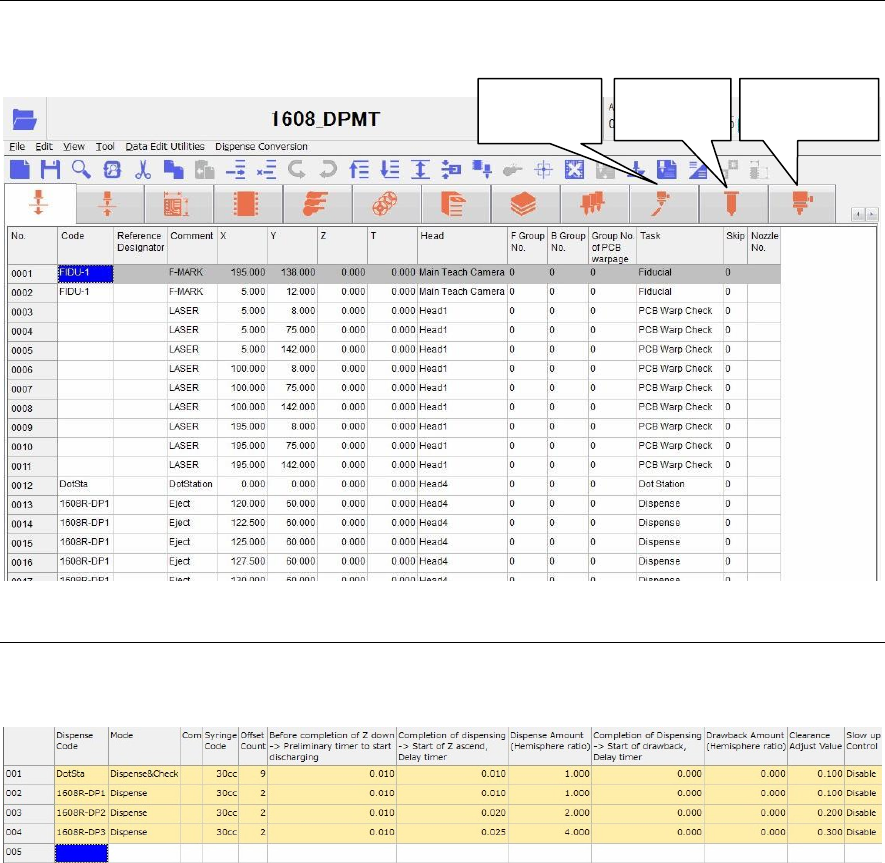
16-1-3-2 Dispense data
The dispense amount is set with the dispense data.
Menu: Dispense Data
Window:
Dispense Code Enter a dispense code.
This dispense code will link with the code of the placement & mark
(program).
Additionally, double-click the [Dispense Code] cell to display the [Dispense
check] (Tool>AdvancedSetting) window.
Note: Do not use the word “DotStation” for this dispense code. Doing so may cause
an error.
Mode Right-click this cell to select a mode.
① When dispensing the dot station, select “Dispense & Check”.
After dispensed, the dispensed portion is captured by the teach camera
to automatically adjust the dispense diameter to the set diameter
(dispense area).
② To dispense onto the PCB, select “Dispense”.
Comment Enter a comment.
Syringe Code Right-click this cell to select a syringe code of the syringe data described later.
Additionally, double-clicking this cell will jump to the syringe data.
Dispense
data
Syringe
data
Dispense
nozzle data