M20_Ope_E - 第476页
Chapter 16 Dispenser 16-6 16-1-3-1 Dispenser related data This dispense related data includes dispense data, syringe data, and dispense nozzle data as described below. 16-1-3-2 Dispense data The dispense amount is set wi…
Chapter 16 Dispenser
16-5
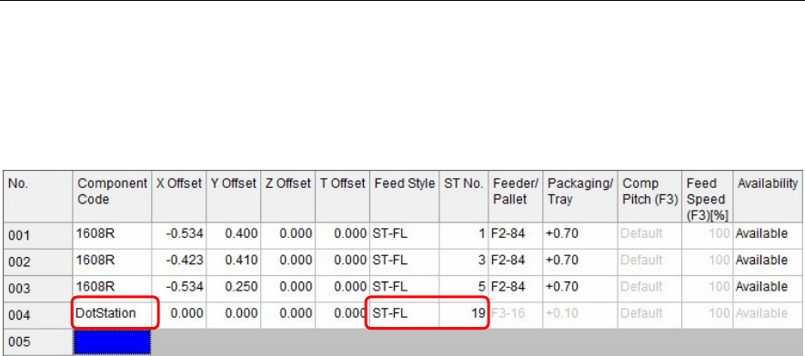
16-1-3 Dot station setting
Set the position where the dot station is installed.
Note, however, that this setting is not required for the D10 dispenser.
Menu: Pickup Data
Action:
① Install the dot station on the feeder bank.
② In [Component Code] of [Pickup data], enter “DotStation”.
③ In [Feed Style], select a feeder bank on which the dot station is installed.
④ Enter [ST No.] on which the dot station is installed.
Note: “DotStation” to be entered in [Component Code] is a specific code.
Carefully check upper and lower case characters when entering “DotStation”.
When you have entered this “DotStation”, cells other than [Feed Style] and [ST No.] become invalid.
Chapter 16 Dispenser
16-6
16-1-3-1 Dispenser related data
This dispense related data includes dispense data, syringe data, and dispense nozzle data as described
below.
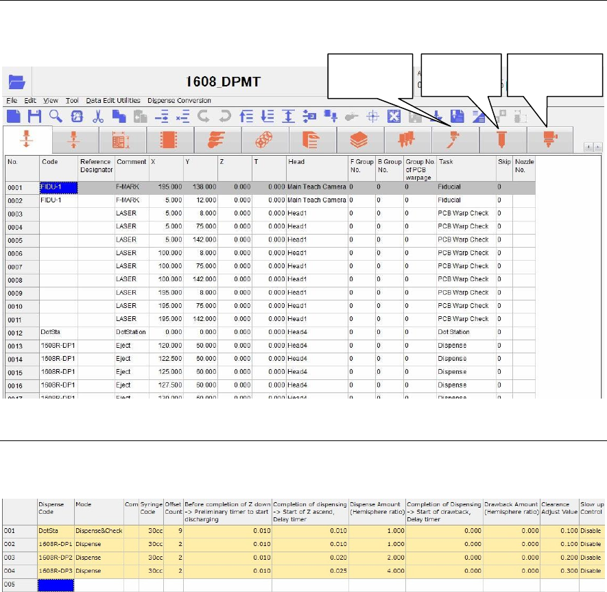
16-1-3-2 Dispense data
The dispense amount is set with the dispense data.
Menu: Dispense Data
Window:
Dispense Code Enter a dispense code.
This dispense code will link with the code of the placement & mark
(program).
Additionally, double-click the [Dispense Code] cell to display the [Dispense
check] (Tool>AdvancedSetting) window.
Note: Do not use the word “DotStation” for this dispense code. Doing so may cause
an error.
Mode Right-click this cell to select a mode.
① When dispensing the dot station, select “Dispense & Check”.
After dispensed, the dispensed portion is captured by the teach camera
to automatically adjust the dispense diameter to the set diameter
(dispense area).
② To dispense onto the PCB, select “Dispense”.
Comment Enter a comment.
Syringe Code Right-click this cell to select a syringe code of the syringe data described later.
Additionally, double-clicking this cell will jump to the syringe data.
Dispense
data
Syringe
data
Dispense
nozzle data
Chapter 16 Dispenser
16-7
Offset Count The set offset count from [X] and [Y] of the reference dispense point on the
PCB is displayed.
When there are no offsets, “1” is displayed and one point expressed by [X]
and [Y] of the dispense point on the PCB is dispensed.
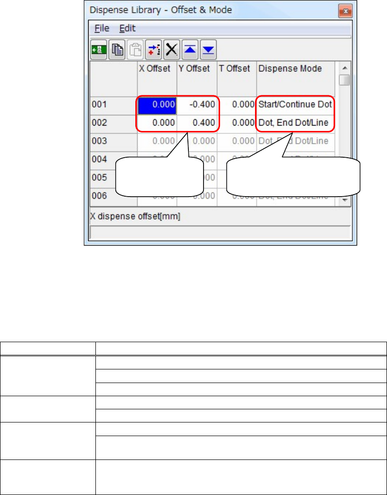
Additionally, double-click this cell to display the [Offset & Mode] window.
In this window, you can set the offsets of the dispense point. Additionally,
you can also set the line dispense.
Note: Consider [X Offset] and [Y Offset] as offsets from [X] and [Y] of the reference
dispense point of the placement & mark (program).
Additionally, determine [X Offset] and [Y Offset] according to the component
size.
Dispense Mode
Dispense mode Contents
Dot, End Dot/Line
Performs the dot dispense.
Ends the dot dispense.
Ends the line dispense.
Start/Continue Dot
Starts the dot dispense.
Continues the dot dispense.
Start/Continue Line
Starts the line dispense.
Continues the line dispense (changes the direction of the line dispense
without moving up of the head).
End Line & Continue
Ends the line dispense (moves up the head once) and continues the dot
dispense or line dispense further. Performs multiple line dispenses
without changing of the dispense code.
Before completion of Z down -> Preliminary timer to start discharging
Set timing, at which the dispense starts before completion of Z moving down.
(Unit: Sec.)
Completion of dispensing -> Start of Z ascend, Delay timer
Set timing, at which Z starts ascending after completion of dispensing.
(Unit: Sec.)
Enter [X Offset]
and [Y Offset].
Right-click this cell to select
a desired [Dispense Mode].