M20_Ope_E - 第480页
Chapter 16 Dispenser 16-10 Syringe Code (Lower) Enter a syringe code. This code will link with the syringe code of the dispense code. Comment Ente r a comment. Nozzle Code Right-click this cell to select a nozzle code of…
Chapter 16 Dispenser
16-9
16-1-3-3 Syringe data
This syringe data contains data related to the dispense material.
Menu: Syringe Data
Window:
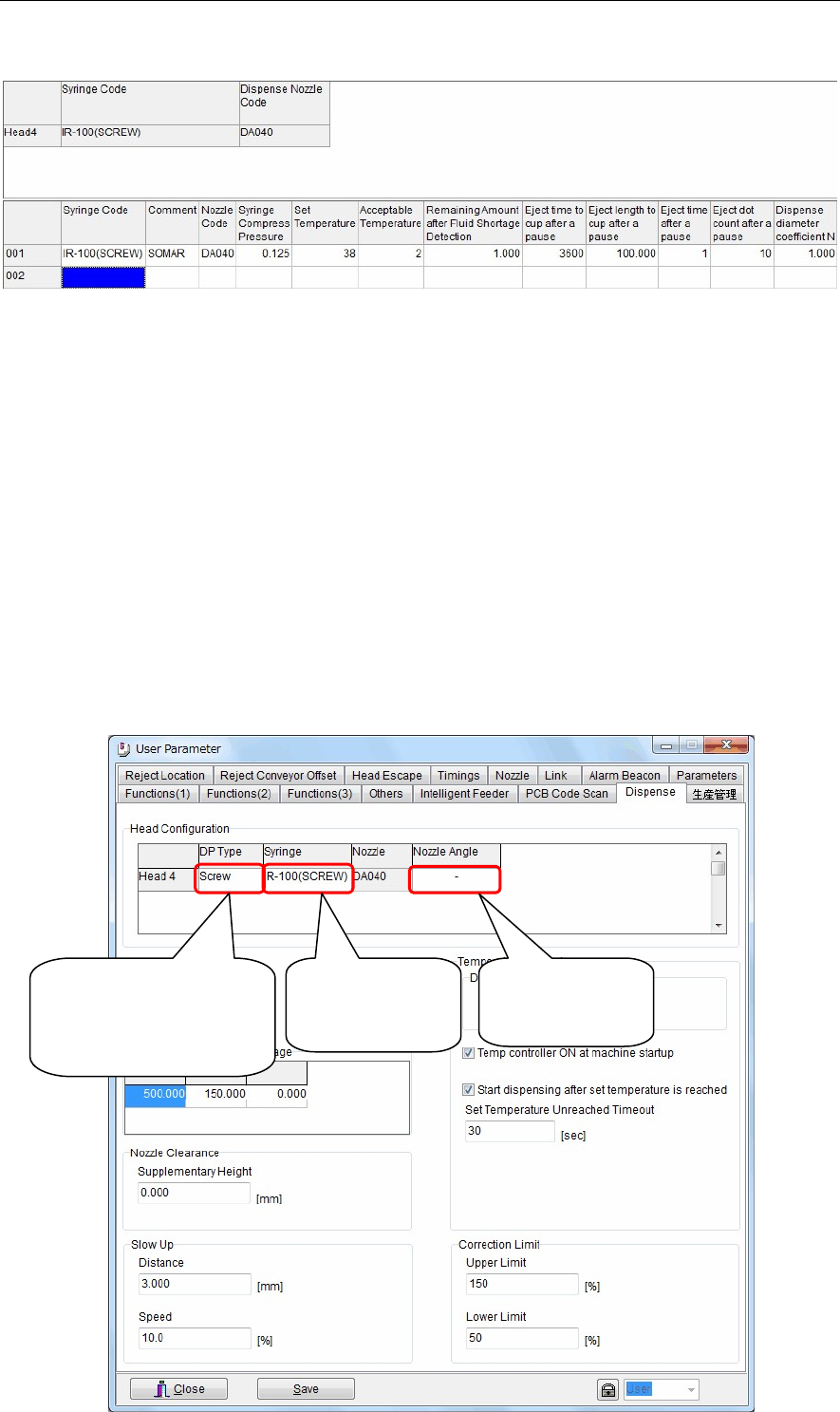
Syringe Code (Upper) Indicates which syringes (syringe codes) are mounted at the respective head
Nos.
Settings can be specified at the System > User parameter > Dispense screen
(see the figure below).
To select syringe codes at this screen, right-click on [Syringe] at the [Head
Configuration] item.
Note: Also right-click on [DP Type] at the screen's [Head Configuration] item, then
select the dispense head types which are mounted on each head.
Be sure to check this information carefully, because accidents such as
collisions, etc., could occur if the installed dispense head type differs from this
setting.
Note: When using twin nozzles, right-click on [Nozzle Angle] at this screen's [Head
Configuration] item, then select the twin nozzles' basic posture.
The twin nozzle "posture at origin return" can be selected as "horizontal 2
points" or "vertical 2 points".
Right-click here,
then select
"Syringe
code".
[Note]
Be sure that the installed
dispense head type
matches the setting.
Select the basic
posture for twin
nozzles.
Chapter 16 Dispenser
16-10
Syringe Code (Lower) Enter a syringe code.
This code will link with the syringe code of the dispense code.
Comment Enter a comment.
Nozzle Code Right-click this cell to select a nozzle code of the dispense nozzle data
described later.
Additionally, double-clicking this cell will jump to the dispense nozzle data.
Syringe Compress Pressure
For screw type dispense heads, set an air pressure level necessary to feed the
dispense material from the syringe to the dispense head. (Unit: MPa)
Note: If this pressure is too high, the post-drip or fluid drip may occur after
dispensing.
Additionally, if the pressure is too low, the dispense material cannot be
supplied to the screw type dispense head at adequate timing.
For pneumatic dispense heads, sets an air pressure level necessary to
discharge the dispense material. (Units: MPa)
Temperature control setting
Sets the dispense head's heater temperature. (Units: °C)
This temperature should be set higher than the room temperature.
Note: The heater and dispense head areas may be extremely hot. Use care to avoid
burn injuries.
Note: Remove the dispense material from its storage area in advance, and allow it to
reach room temperature (approximately) before using it.
Temperature tolerance
Sets the dispense head's heater temperature tolerance. (Units: °C)
Production must not occur until the heater temperature is within the tolerance
range (±).
Remaining Amount after Fluid Shortage Detection
Set an amount that can be dispensed after the fluid shortage has been
detected.
Eject time to cup after a pause
The dispense material is ejected to the cup and discharged unless it is
dispensed for a period of time set in this cell.
(Unit: Sec.)
Eject length to cup after a pause
Set a length to eject to the cup as described above.
(Unit: mm)
Eject time after a pause The dispense material is ejected to the dot station unless it is dispensed for a
period of time set in this cell.
(Unit: Sec.)
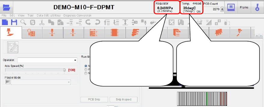
Indicates the current
"syringe pressure" (the
setting value is indicated
in parentheses beneath this
value).
Indicates the current
"heater temperature" (the
setting value is indicated
in parentheses beneath this
value).
Chapter 16 Dispenser
16-11
Eject dot count after a pause
Set the eject dot count for the dot station as described above.
It is recommended to perform 3 to 5 eject dots.
Note: When ejecting to cup after a pause, the dispense material may stick to the
nozzle tip.
To remove this sticking dispense material, perform the eject dots to the dot
station continuously.
Dispense diameter coefficient N
See [Dispense Amount (Hemisphere ratio)] of the dispense data described
previously.
This coefficient is determined by the dispense material.
Fluid shortage detection magnet ASSY.
The dispense head uses a magnet to detect the dispense material fluid shortage in the syringe.
Attach the magnet ASSY to the plunger inside the syringe and set it on the head.
Note: When the syringe is replaced after the fluid shortage has been detected, be careful not to dispose of the
magnet ASSY together with the syringe.
Blow the air from the syringe tip to take out the plunger and magnet ASSY.
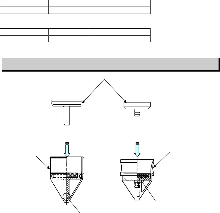
There are two kinds of magnet ASSYs available.
Select appropriate plunger and magnet ASSY suitable for manufacturer’s syringe to be used.
For Iwashita Engineering’s plunger
Syringe capacity PART NO. Part name
30 cc LE6-M5F2K-100 MAGNET ASSY.(30 I/E)
For Musashi Engineering’s plunger
Syringe capacity PART NO. Part name
30 cc LE6-M5F2K-200 MAGNET ASSY.(30 M/E)
Magnet ASSY. attaching procedure
Push the magnet ASSY in the direction shown in the Fig. below until the part A is in contact with the
plunger.
Ma
g
net ASSY.
A
A
Iwashita Engineering’s
plunger
Musashi Engineering’s
plunger