M20_Ope_E - 第486页
Chapter 16 Dispenser 16-16 ③ Double-click [Offset Count] to di splay the [Offset & Mode] window. ④ In this window, you can set the offsets to be dispensed onto the dot station. Recommended values : Dispense to 32 poi…
Chapter 16 Dispenser
16-15
16-3 Dispense check
16-3-1 Dispense check
In this dispense check, the dispense status is captured by the teach camera and its image is processed to
check whether or not the dispense area is proper.
When the check result is determined as NG, it is fed back to the dispense conditions to automatically
correct the dispense area.
This process is called “dispense correction (retry)”.
16-3-1-1 Placement & mark (program) setting
Normally, the dispense check is performed while dispensing onto the dot station. However, when the
conditions, such as dispense material color and PCB color are satisfied, the dispense check is performed
even while dispensing onto the PCB.
Menu: Placement & Mark (program)
Action:
⑧ Right-click [Task] to select a desired task from the table shown below.
[Task] Dispense location
Dot Station Dot station
Dispense Check PCB
⑨ The following describes the dispense check with the dot station. So, select [Dot Station].
16-3-1-2 Dispense data setting
Menu: Dispense Data
Action:
① Set the dispense conditions for the dispense check in the same manner as the normal dispense data.
Note: At this time, set the same conditions as the dispense conditions for dispensing onto the PCB.
This dispenses onto the PCB under the dispense conditions, the dispense check of which has been
completed.
(The concept is that the dispense amount which has been dispensed onto the dot station and checked is
directly copied onto the PCB.)
In particular, it is recommended to set the dispense conditions with the minimum dispense amount.
(This is intended to control the minimum dispense amount when viewed from the quality aspect.)
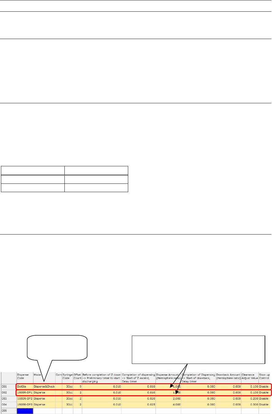
② Right-click [Mode] to select “Dispense & Check”.
Select “Dispense
& Check”.
Set the same dispense conditions as those for
dispensing PCB. In particular, set the dispense
conditions with the minimum dispense amount.
Chapter 16 Dispenser
16-16
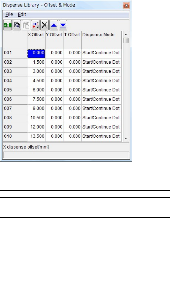
③ Double-click [Offset Count] to display the [Offset & Mode] window.
④ In this window, you can set the offsets to be dispensed onto the dot station.
Recommended values: Dispense to 32 points with X Offset pitch of 1.5 mm as described in the table
below.
NO. X Offset Y Offset
T Offset Dispense Mode
001 0.000
0.00 0.00
Start/Continue Dot
002 1.500
0.00 0.00
Start/Continue Dot
003 3.000
0.00 0.00
Start/Continue Dot
004 4.500
0.00 0.00
Start/Continue Dot
005 6.000
0.00 0.00
Start/Continue Dot
006 7.500
0.00 0.00
Start/Continue Dot
007 9.000
0.00 0.00
Start/Continue Dot
008 10.500
0.00 0.00
Start/Continue Dot
009 12.000
0.00 0.00
Start/Continue Dot
010 13.500
Start/Continue Dot
·
·
·
·
·
·
·
·
·
·
·
·
·
·
·
45.000
0.00 0.00
46.500
0.00 0.00
Dot, End Dot/Line
Chapter 16 Dispenser
16-17
16-3-1-3 Dispense Library - Dispense Check setting
Menu: Dispense Data > Dispense Library - Dispense Check
Action:
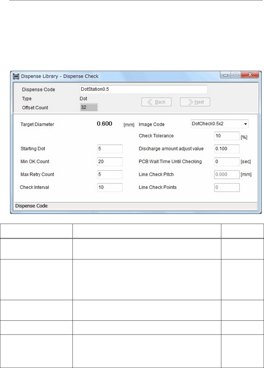
① Double-click [Dispense Code] of the dispense data to display the Dispense Library - Dispense Check
window.
Additionally, when clicking “Tool>Advanced Setting” of the System menu at the upper portion of
the window, the Dispense Library - Dispense Check window will appear.
② In this window, you can set dispense check parameters.
Item Contents
Recommended
value
Starting Dot
Specify what dispense point the dispense check is started.
Note that the dispense diameter and dispense shape of several
points after the dispense has started do not become stable.
5 (th point)
Min OK Count
When the image process of the dispense points more than this
count is determined as OK, the result is determined as OK. The
image process results of the dispense points are then
accumulated (averaged) to output the final results.
The reference dispense points for the dispense check are 2/3 of
the total count.
20 points
Max Retry Count
Specify maximum counts for the dispense correction.
(Retry counts) When this count is "0", only the dispense check
is performed and the correction is not performed.
5 (counts)
Check Interval
Specify a PCB interval, at which the dispense check is
performed.
Example: 10
(PCBs)
Check Tolerance [%]
A tolerance value that the dispense check is determined as OK.
When the accumulated (averaged) dispense area enters the
range of this check tolerance value (±), this is determined as
OK. The dispense area to be used as reference is calculated
from [Target Diameter] of the Image Library (image data).
10 (%)