M20_Ope_E - 第491页
Chapter 16 Dispenser 16-21 16-3-1-5 Dispense correction by means of 1/2 convergence method The following describes the principle of the dispense correction. Example: ① First, the dispense amount (hemisphere volume) set f…
Chapter 16 Dispenser
16-20
Item Unit Contents Recommended value
Expected width mm
Enter a desired line dispense width (line dispense
width to be adjusted in the adjustment of the dispense
check).
Normally, the line dispense width is larger than the
outer diameter of the nozzle.
Outer diameter of
nozzle or more
Width Perm %
A permissible value of the line dispense width, the
image process of which is determined as OK.
This value is expressed by ±% value based on the
expected width.
20%
Gain ― Teach camera gain 150
Offset ― Teach camera offset 200
Teach Camera Light
Inside Light
― Teach camera light, inside light 8
Teach Camera Light
Outside Light
― Teach camera light, outside light 0
Note: It is recommended to use only [Inside Light] of the teach camera light.
If [Outside Light] is used, the edge of the dispense material that has been dispensed may be blurred.
Note: Move the teach camera to the dispense point on the dot station to perform the image test.
Make sure that the square frame of the image test result is in contact with the edges of the dispense
material that has been dispensed.
The long side of the square frame of this image test result becomes the maximum diameter of the
dispense diameter while the short side becomes the minimum diameter of the dispense diameter.
If the square frame of the image test result is not in contact with the dispense material that has been
dispensed, adjust the light.
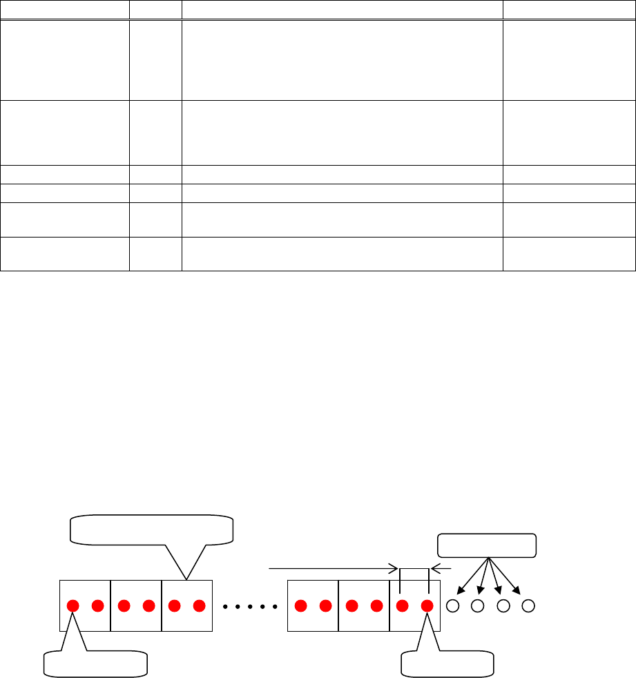
Dispense status on the dot station when dispensed with the recommended values entered.
Dispense offset pitch
1.500 (mm)
1 image process block
5th shot 32nd shot
Pre-dispense
Chapter 16 Dispenser
16-21
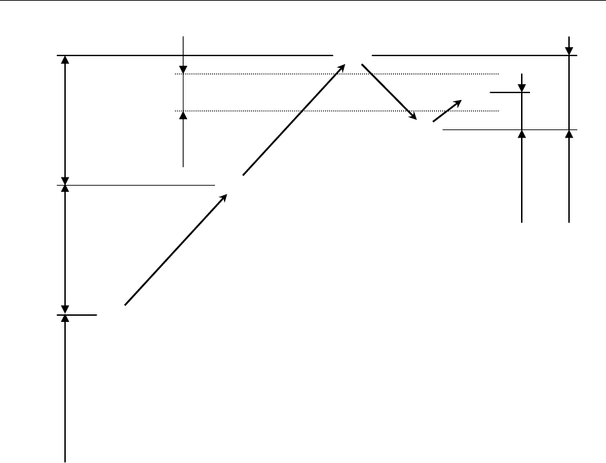
16-3-1-5 Dispense correction by means of 1/2 convergence method
The following describes the principle of the dispense correction.
Example:
① First, the dispense amount (hemisphere volume) set for the dot station is dispensed to perform the
dispense check. (① in the Fig. above)
② Since the dispense area is smaller than the range of the check tolerance value [±%], the set correction
amount is added to the dispense amount to retry the dispense check. (② in the Fig. above.)
③ Since the dispense area is still smaller than the range of the check tolerance value [±%], the set
correction amount is further added to the dispense amount to retry the dispense check. (③ in the Fig.
above)
④ Since the dispense area exceeds the range of the check tolerance value [±%], 1/2 of the previous
correction amount is subtracted from the dispense amount to retry the dispense check. (④ in the Fig.
above)
⑤ Since the dispense area becomes smaller than the range of the check tolerance value [±%], 1/2 of the
previous correction amount (1/4 of the original correction amount) is added to the dispense amount
to retry the dispense check.
The dispense area then enters the range of the check tolerance value [±%]. (⑤ in the Fig. above)
Note: Every time the dispense correction direction (positive/negative) is changed, the correction value is
reduced by half (1/2).
This correction method is called “1/2 convergence method”.
①
②
③
④
⑤
Check
tolerance
[±%]
Correction amount
Correction
amount /4
Set dispense amount
(Hemisphere volume)
Correction amount
Correction
amount /2
Chapter 16 Dispenser
16-22
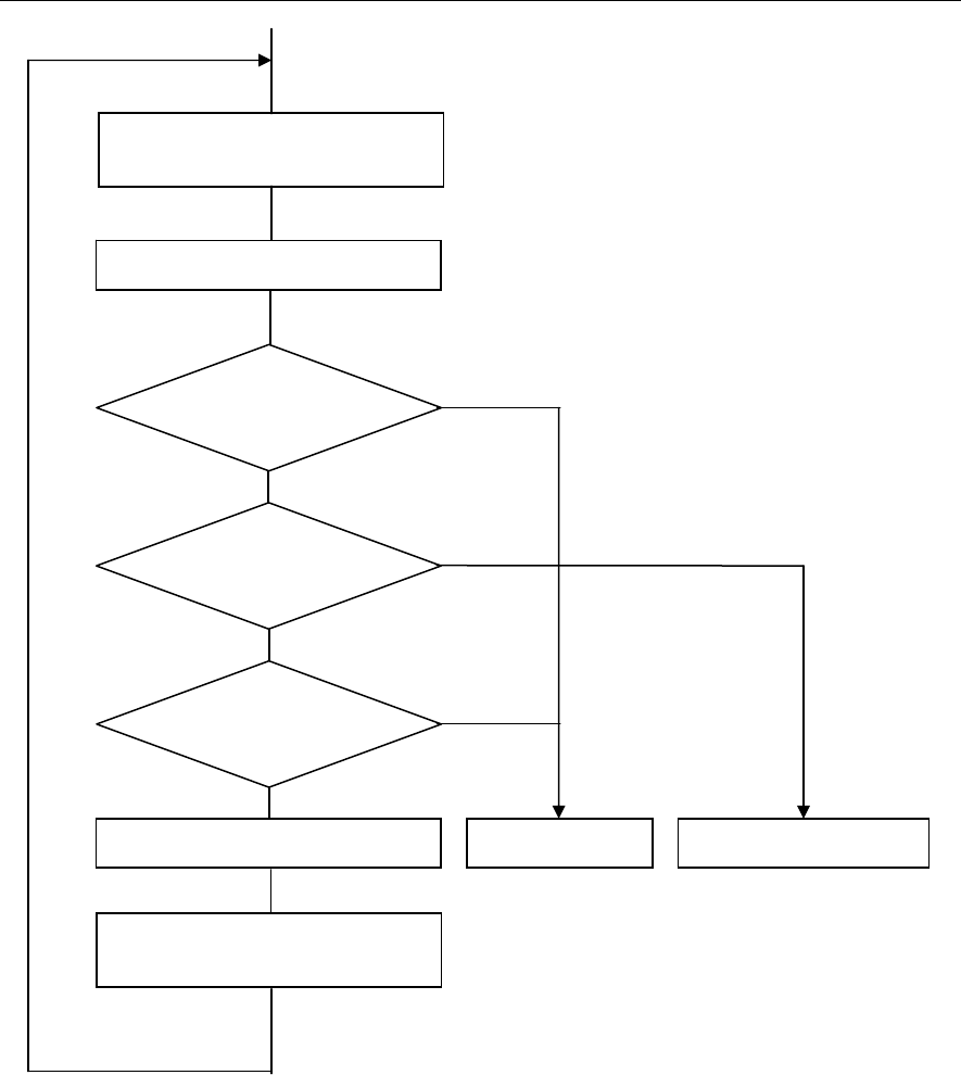
16-3-1-6 Sequence of dispense correction
No
Yes
Yes
No
Yes
No
Dispense check
(Dot/line dispense)
Dispense position change or dot
station paper feed
Is min. check count OK?
Is image process OK?
Are dispense area and line
dispense width in average
allowable ran
g
e?
Is max. check count over?
PCB dispense start Alarm stop Dispense correction
Retr
y
Image process