M20_Ope_E - 第493页
Chapter 16 Dispenser 16-23 16-3-1-7 Dispense check operation It is recommended to start the production after the dispense check has been performed on the dot station and it has been confirmed th at the dispense area is O…
Chapter 16 Dispenser
16-22
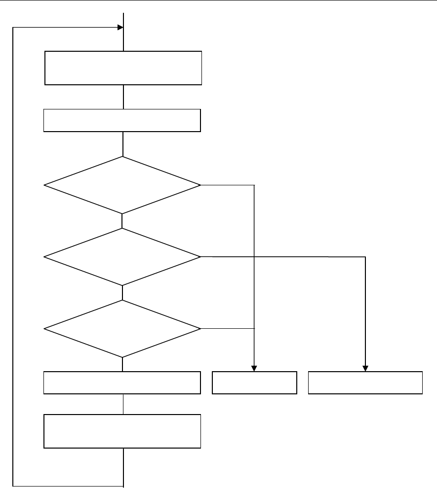
16-3-1-6 Sequence of dispense correction
No
Yes
Yes
No
Yes
No
Dispense check
(Dot/line dispense)
Dispense position change or dot
station paper feed
Is min. check count OK?
Is image process OK?
Are dispense area and line
dispense width in average
allowable ran
g
e?
Is max. check count over?
PCB dispense start Alarm stop Dispense correction
Retr
y
Image process
Chapter 16 Dispenser
16-23
16-3-1-7 Dispense check operation
It is recommended to start the production after the dispense check has been performed on the dot station
and it has been confirmed that the dispense area is OK.
There are two kinds of methods: [Auto] or [Manual] available as described below.
Auto:
① Press the START
switch to run the program. When the dispense on the dot station starts, press the
STOP
switch.
② At this time, open the message display at the lower portion of the window and the overlay.
③ Repeat the dispense correction (retry). When the dispense check is determined as OK, press the
START
switch to restart the production. From the next production onward, it is not necessary to
stop the production for the dispense check.
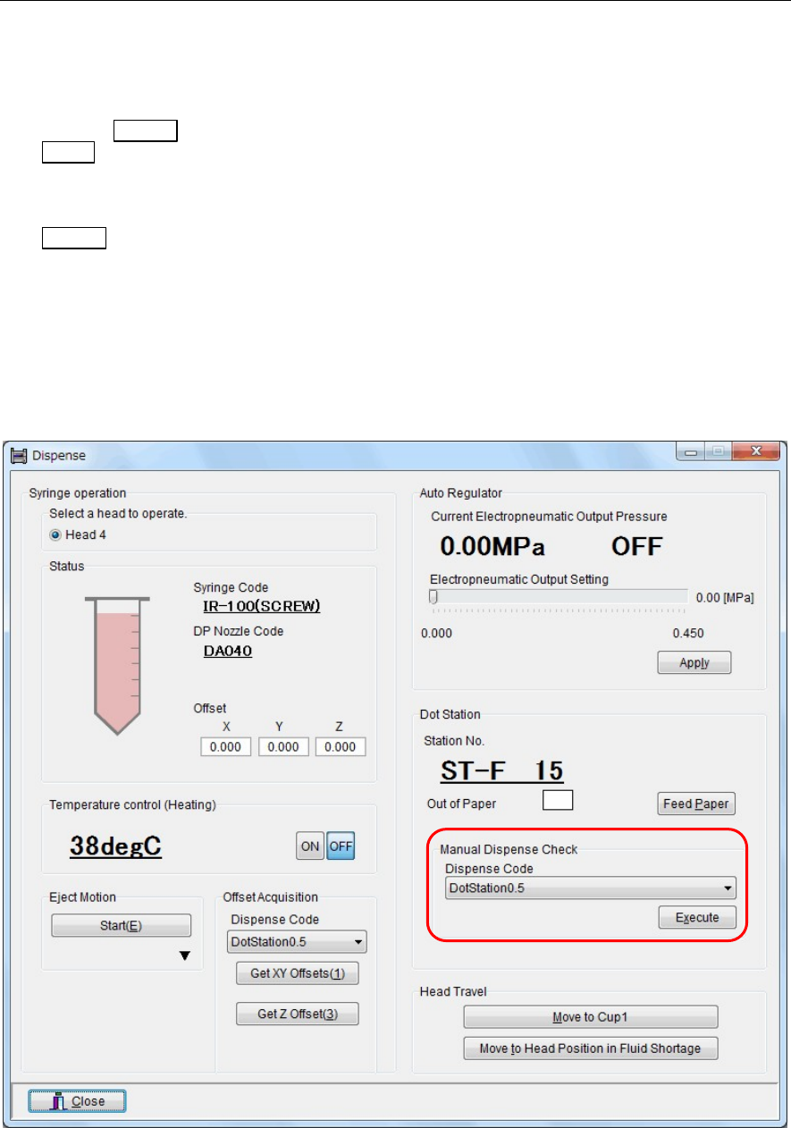
Menu: Manual>Dispense
Manual:
① Open the “Manual>Dispense” window.
② At this time, open the message display at the lower portion of the window and the overlay.
③ In this window, select a dispense code in the [Manual Dispense Check] area, and then click the
<Execute> button.
④ Perform the dispense check on the dot station.
⑤ Repeat the dispense correction (retry). When the dispense check is determined as OK, start the
production.
Chapter 16 Dispenser
16-24
Note: An [Auto] dispense check occurs during production when the Placement & mark (program) contains a
"dispense check" (dot station) step.
Therefore, the [Manual] method should be used at dispense check tests.
Contents of message display
[AR]・・・ Dispense area (square mm x 1000)
[LS]・・・ Maximum dispense diameter (μm)
[SS]・・・ Minimum dispense diameter (μm)
[SD]・・・ Dispense area ratio (%)
Note ①: The [AR], [LS], [SS], and [SD] lines on the message display show the image process result of one dispense
point. The image process result OK is displayed in blue while the result NG is displayed in orange.
The dispense area ratio, the image process result of which is determined as OK (displayed in blue), is
accumulated (averaged) to judge whether or not the calculation value is in a range of [Check
Tolerance](±%).
Note ②: If the dispense check is not determine as OK (not converged) even after the dispense correction (retry)
has been repeated, adjust the dispense amount.
Adjust the dispense conditions of the dispense data so that [LS] and [SS] on the message display get close
to [Target Diameter] of the Image Library (image data) and [SD] gets close to 100%.
(Make the adjustment so that many blue image process result OK lines are shown on the message
display.)
Note ③: If the dispense conditions for the dispense check have been changed, change also the data of the same
dispense conditions for dispensing onto the PCB accordingly.
These conditions are always considered as a set. Be sure to set the same dispense conditions.
Note ④: When there is a dispense check (dot station) step in the placement & mark (program), this dispense check
affects the subsequent dispense steps.
Subsequently, when there is the second dispense check (dot station) step, the previous dispense check is
deleted, the dispense check is updated to a new dispense check, and this dispense check affects the
subsequent dispense steps.
For example, you can program like, “Dispense check with small dispense amount ⇒ Dispense with small
dispense amount ⇒ Dispense check with large dispense amount ⇒Dispense with large dispense
amount”.