M20_Ope_E - 第514页
Chapter 17 Multi Conveyor 17-4 PCB Data The PCB data editor shows the multi conveyor function settings in the screen below. 【 Menu 】 PCB Data > 2 nd page To avoid the laser sensor from the “Cutout” of th e board, inpu…
Chapter 17 Multi Conveyor
17-3
【Operation】
1. In case of machines M10 and D10, select the conveyor to be used as “Entrance” or “Exit” in the
system parameter: “Buffer on 2Drive Conveyor” for using 2 drive conveyor (board length330mm to
420mm) (see below).
This selection setting is not necessary for M20 machine.
2. Board flow direction can be changed in the system parameter “Board Flow”.
3. Save the system parameter and close the screen after changes.
4. The machine must be shut down and turned on the power again to be effective the changes.
【NOTE】 The operator who is “Forbidden” to change the system parameter in “Management > Operator
Management” is not allowed to change the settings accordingly.
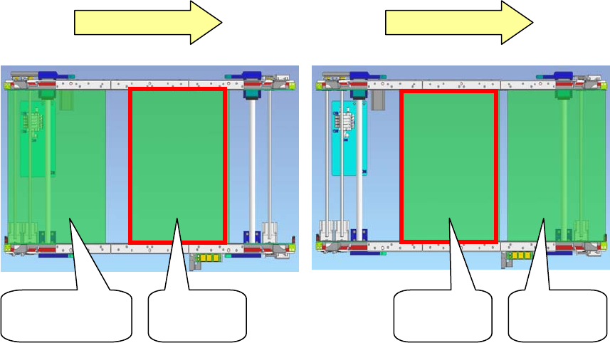
Left to Right Left to Right
Board on
Entrance buffer
Production
board
Production
board
Board on
Exit buffer
Chapter 17 Multi Conveyor
17-4
PCB Data
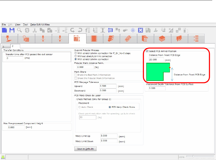
The PCB data editor shows the multi conveyor function settings in the screen below.
【Menu】 PCB Data > 2
nd
page
To avoid the laser sensor from the “Cutout” of the board, input “Distance from Front PCB Edge” in
the screen of PCB Arrival Position to change the head position in conveyor width direction.
【Operation】
1. Check the box “Select PCB Arrival Position”.
2. “Distance from Front PCB Edge” column will be enabled. (The default value is 20mm).
3. Input the distance from front board edge to specify the position where the laser sensor escapes
from the “Cutout”.
The head assembly (laser sensor) moves to the specified position to detect the arriving board.
Chapter 17 Multi Conveyor
17-5
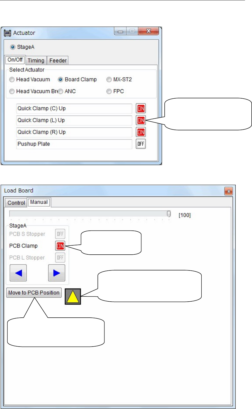
Manual Operation
The manual operation screen for the multi conveyor is shown below.
【Menu】 Manual > Actuator > On/Off > Board Clamp
【Menu】 Manual > Load Board > Manual
Activate “Center”, “Left”
or “Right” Quick Clamp
individually.
Turn on and off
the board clamp
The color will be changed from
black to yellow when the laser
sensor detects the board.
Head assembly (laser sensor)
moves to the position of the
board arrival detection.