M20_Ope_E - 第515页
Chapter 17 Multi Conveyor 17-5 Manual Operation The manual operation screen for th e multi conveyor is shown below. 【 Menu 】 Manual > Actuator > On/Off > Board Clamp 【 Menu 】 Manual > Load Board > Manual A…
Chapter 17 Multi Conveyor
17-4
PCB Data
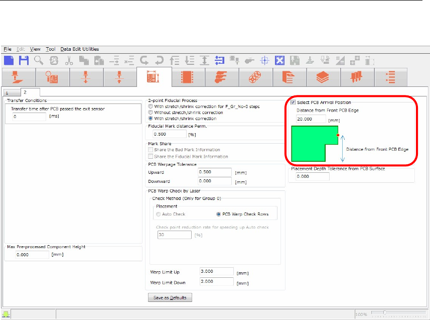
The PCB data editor shows the multi conveyor function settings in the screen below.
【Menu】 PCB Data > 2
nd
page
To avoid the laser sensor from the “Cutout” of the board, input “Distance from Front PCB Edge” in
the screen of PCB Arrival Position to change the head position in conveyor width direction.
【Operation】
1. Check the box “Select PCB Arrival Position”.
2. “Distance from Front PCB Edge” column will be enabled. (The default value is 20mm).
3. Input the distance from front board edge to specify the position where the laser sensor escapes
from the “Cutout”.
The head assembly (laser sensor) moves to the specified position to detect the arriving board.
Chapter 17 Multi Conveyor
17-5
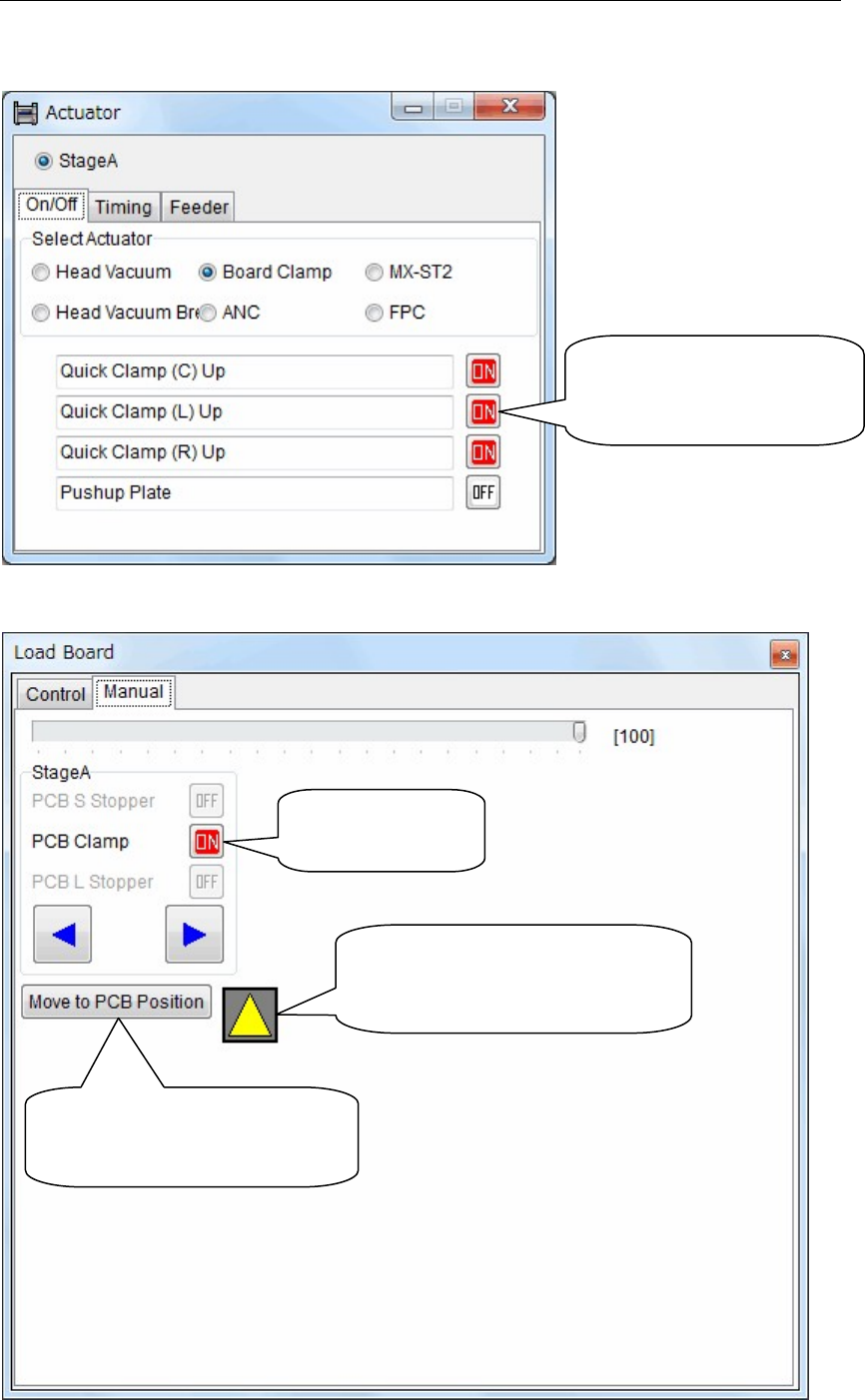
Manual Operation
The manual operation screen for the multi conveyor is shown below.
【Menu】 Manual > Actuator > On/Off > Board Clamp
【Menu】 Manual > Load Board > Manual
Activate “Center”, “Left”
or “Right” Quick Clamp
individually.
Turn on and off
the board clamp
The color will be changed from
black to yellow when the laser
sensor detects the board.
Head assembly (laser sensor)
moves to the position of the
board arrival detection.

YAMAHA SMT Assembly System
Y
AMAHA MOTOR CO., LTD Robotics Operations
127 Toyooka, Kita-ku, Hamamatsu, Shizuoka 433-8103, Japan
Telephone 81-53-525-7061 Facsimile 81-53-525-8351
All rights reserved. No part of this publication may be reproduced in any form without the permission
of YAMAHA MOTOR CO., LTD. Information furnished by YAMAHA in this manual is believed to be reliable.
However, no responsibility is assumed for possible inaccuracies or omissions.
If you find any part unclear in this manual, please contact YAMAHA or YAMAHA sales representatives.
Surface Mounter
Version 900770.R05
Machine Software Operation Manual April, 2016