M20_Ope_E - 第55页
Chapter 2 Creating and Editing a Program 2-11 2-2-2 Teach Entry Teach entry allows for teaching c oordinate data to the mounter. Teach Entry using the Mouse Teach entry in use of the mouse allows the dr iving axes to mov…
Chapter 2 Creating and Editing a Program
2-10
2-2-1-3 Keyboard Entry & Choose from List
There are several data entry methods. This section describes keyboard entry and choose from list used
for direct data entry to an entry field.
Prior to making a keyboard entry or choose-from-list entry to a grid editor, the cell
to enter data must be selected.
Keyboard Entry
Keyboard entry means direct data input from the keyboard. Typically used for entry of program
name, comment, reference designator, or operator name.
Choose from List
When there are pre-registered choices for entry, you can merely make a choice with the mouse.
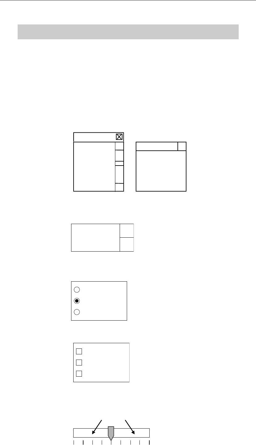
There are five choose-from-list styles:
Combo box: A list of available choices is shown. Click a choice and it will be entered
to the entry field.
(Item 4)
(Item 3)
(Item 2)
(Item 1)
(Item 1)
(Item 2)
(Item 3)
Spin box: Click scroll arrows to select an item. Typing directly from the keyboard
is also available.
(Item)
Radio button: Represents mutually exclusive choices. Only one item is selectable at a
time.
(Item 3)
(Item 2)
(Item 1)
Check Box: Click an item to select. You can select as many items as needed.
(Item 3)
(Item 2)
(Item 1)
Slider: Drag the vertical bar to a new setting. The current value is shown to the
right of the scale. Clicking the area shown with the arrows moves the
vertical bar for a division of the graduation.
4
Chapter 2 Creating and Editing a Program
2-11
2-2-2 Teach Entry
Teach entry allows for teaching coordinate data to the mounter.
Teach Entry using the Mouse
Teach entry in use of the mouse allows the driving axes to move according to the mouse
movement. When teaching, do not stick head, hands, or other parts of the body inside the
mounter. Serious injury can result. Also make sure non-operators are a safe distance from
the machine.
Before starting teach, make sure no foreign obstacles are left in the mounter or the tray feeder.
Otherwise, costly machine damage can occur.
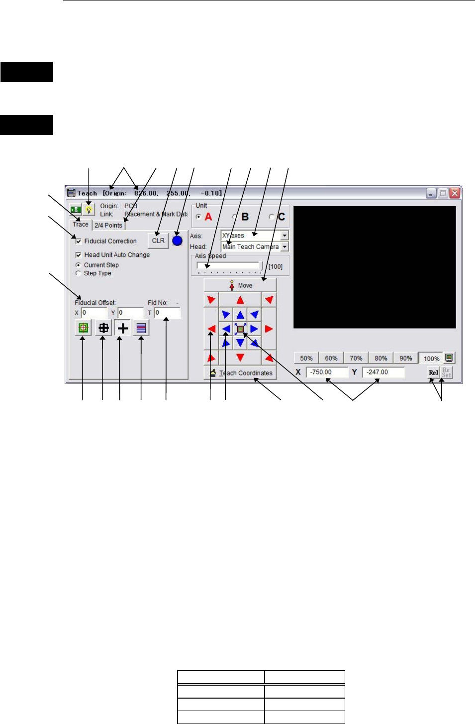
Window:
1. Origin: Indicates the origin relative to which the obtained coordinates are
defined. The origin’s coordinates from the machine origin are shown
on the title bar.
3. Axis: Specify axis/axes whose coordinate to teach (XY axes/Z axis/T axis).
4. Head: Select a head to use for teaching.
For “XY axes”, select one from Head1 to Head4 (or Head1 to Head6), or
Main Teach Camera .
For “Z axis”, select one from Head1 to Head4 (or Head1-Head6).
5. Axis Speed/Head Travel:
Specify head movement speed (Smooth mode) or head inching
increment (Inching mode).
* Increment: 1% (maximum=100%)
6. Current Coordinates: Indicates the current teach coordinates. Displayed items vary
depending on the specified axis/axes.
Axis Coordinates
XY axes X and Y
Z axis Z
T axis T
Warning
Caution
1
9
8
4
7
5
11
10
16
17
18
19
20
21
12
24
22
15
6
3
23
13
14
Chapter 2 Creating and Editing a Program
2-12
7. <Rel/Abs>, <Reset>buttons:
First click [Rel] button, then [Reset] button to initialize current
coordinates as a customized origin to teach. Click [Abs] button to be
back to the original coordinates referenced from a programmed origin.
8. Navigator Matrix - Outer Arrow Buttons:
Press down an arrow button so the head moves to the direction of the
arrow with the axis speed specified at “Axis Speed”.
9. Navigator Matrix - Inner Arrow Buttons:
Press down an arrow button so the head moves to the direction of the
arrow. Head travels for the distance specified at “Head Travel” by a
click action, and the head movement gradually becomes fast as you
keep pressing an arrow button. To stop the head, release the mouse.
10. Teach Coordinates: After aligning the teach camera to the desired coordinates, click this
button to acquire the coordinates (one-point teach). Use this button also
to acquire coordinates after scanning a programmed step with
Trace>Move and adjusting the coordinates. When [Fiducial Correction]
option is selected, coordinates with fiducial offset appended are
acquired.
P
One
11. Fiducial Lamp: This lamp turns yellow when the fiducial compensation is applied to
the current coordinates.
12. <CLR> button: Clears all the acquired fiducial offsets.
13. [Trace] tab: Allows the specified head to trace the specified
(placement/pickup/fiducial) program steps. When the main/aux.
teach camera is specified, each traced step can be monitored on the
Vision Window. Click an X/Y/Z/T field of the program step and
right-click the mouse. The Teach dialog box opens. Then specify what
to trace.
14. Fiducial Correction: With this option selected, before the mounter traces the specified step,
the mounter scans fiducials to compensate the specified step.
Current Step
: Traces only the current step. Click <Move> button to execute. Z
coordinate can be traced also. Select an axis/axes under [Axis].
Step Type
: Traces specified type of steps from the current step to the end of the
program. Click <Step Type> button and select a type of steps from the
below choices:
<PCB>: Traces placement steps.
<Feeder>: Traces pickup points (only for ST-F/R).
<Fiducial>: Traces fiducial steps.
After specifying what to trace, click <Move> button at each step. Z
coordinate can be traced also. Select an axis/axes under [Axis].
15. <Move> button: Allows the specified head/camera to move to the coordinates on
specified program step under the conditions of [Trace] tab.
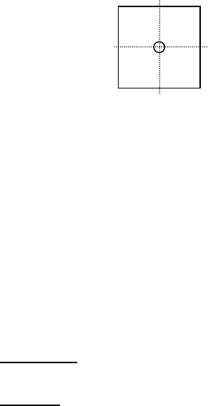
16. Fiducial Center Teach When < Fiducial Center Teach > in the teach window is clicked while
you are at a fiducial mark line, the center coordinates of the mark will
be detected. A message 「Do you want to teach coordinates?」 appears
when the center coordinates are detected, so click <Yes> if you want to
reflect the detected center coordinates to the program. If not, click
<No>.
17. Guide Window: When “XY axes” is specified for [Axis] and “Main Teach Camera” is
specified for [Head], pressing <Guide Window> button provides the