M20_Ope_E - 第58页
Chapter 2 Creating and Editing a Program 2-14 ⑧ Click in the navigator matrix again for final alig nment. If necessary, adjust the axis speed for [Axis Speed]. For fine teaching, use Inner Allow buttons. When the first t…
Chapter 2 Creating and Editing a Program
2-13
guide window outlining the component on the Vision Window. This
component outline is based on the component image data. The guide
window is available only when the component is processed with
single-view process and at the same time the component’s placement
angle T is either 0, 90, or 180.
18. Cross Hairs: Displays cross hairs on the Vision Window. The intersection of the
cross hairs corresponds to the teach point.
19. Search Line: See Chapter 9 Running a Job > Line Search (ASJ).
20. Fiducial Offset: Shows the current fiducial offset in performing <Fiducial Move>
operation (Y, Y, and T).
21. Fid No.: Shows [Fiducial] setting of the current program step (Placement &
Mark Data).
22. Set Illumi.: Enter the illumination setting for teach entry in the Illumination dialog
box (Teach>SetIllumi.). You can register up to seven illumination
settings for different purposes (teaching the PCB, feeder stations, tray,
and others). Enter the illumination setting as follows: Click a button
under [Group] and type in any name for identifying the setting. Drag
the sliders appropriately and click <Execute> button to activate the
setting. Check the Vision Window to see if the video image is clearly
monitored. If not, adjust the sliders and re-click <Execute> button.
When the adjustment is complete, under [Group], click the next button
and enter the setting the same way.
23. Wide View: Allows the teach camera to capture nine views and display the
assembled view as one picture in the monitor so that you can observe
wider area of a PCB.
Nine views are assembled from the standard center view and the eight
surrounding views which can be seen by the inner arrow buttons.
The wide view will be cancelled when you operate an axis, press the
<Move> button, or press the zoom buttons.
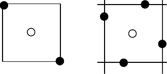
24. [2/4 Points] tab: When “XY axes” is specified for [Axis], specify the number of teach
points.
P
Four points (lines)
Two
P
The system calculates the center coordinates P. See the following Action
section for the procedure to use this feature.
Note: When performing the two-/four-point teach, do not use <Teach
Coordinates> button.
Action: The following shows how to teach X, Y coordinates on a PCB using the main teach camera
(two-point teach):
① In the program editor, click the X/Y field of the program step for which to perform teach.
② Click Tool>Teach or right-click in a cell you want to teach. The Teach dialog box appears.
③ Under [Axis], select “XY axes”.
④ Under [Head], select “Main Teach Camera”. The camera lighting is turned on.
⑤ Click [2/4 Points] tab. Select <Two>.
⑥ Click in the navigator matrix (Outer Arrow buttons) to assign head moving direction. The
head starts to move. While keep pressing the left button of the mouse, the head keeps
moving.
⑦ While watching both the actual head movement and the Vision Window, adjust head moving
direction by moving the mouse. Continue until the head comes close to the specified step.
Chapter 2 Creating and Editing a Program
2-14
⑧ Click in the navigator matrix again for final alignment. If necessary, adjust the axis speed for
[Axis Speed]. For fine teaching, use Inner Allow buttons. When the first teach point is aligned
to the camera center, click to stop the head. Click <1st Point> button.
⑨ To obtain the second teach point, repeat steps 7 through 8.
⑩ When the second teach point is aligned to the camera center, click to stop the head. Click
<2nd Point> button. The coordinates of the component center are calculated and entered to
the X, Y fields of the current program step.
⑪ If there are other steps to teach, repeat steps 1 through 11 to teach them. Then click <Close>
button to end.
Switching between Different Windows for Teach Entry
You may open several editor/library windows at a time and switch the line to teach between
windows. In this case, you don’t have to close and reopen the Teach dialog box each time you
switch to a different window. Instead, when you switch to a different window, select the
coordinate setting field and right-click the mouse. This allows the system to identify in which
window you are going to perform teach.
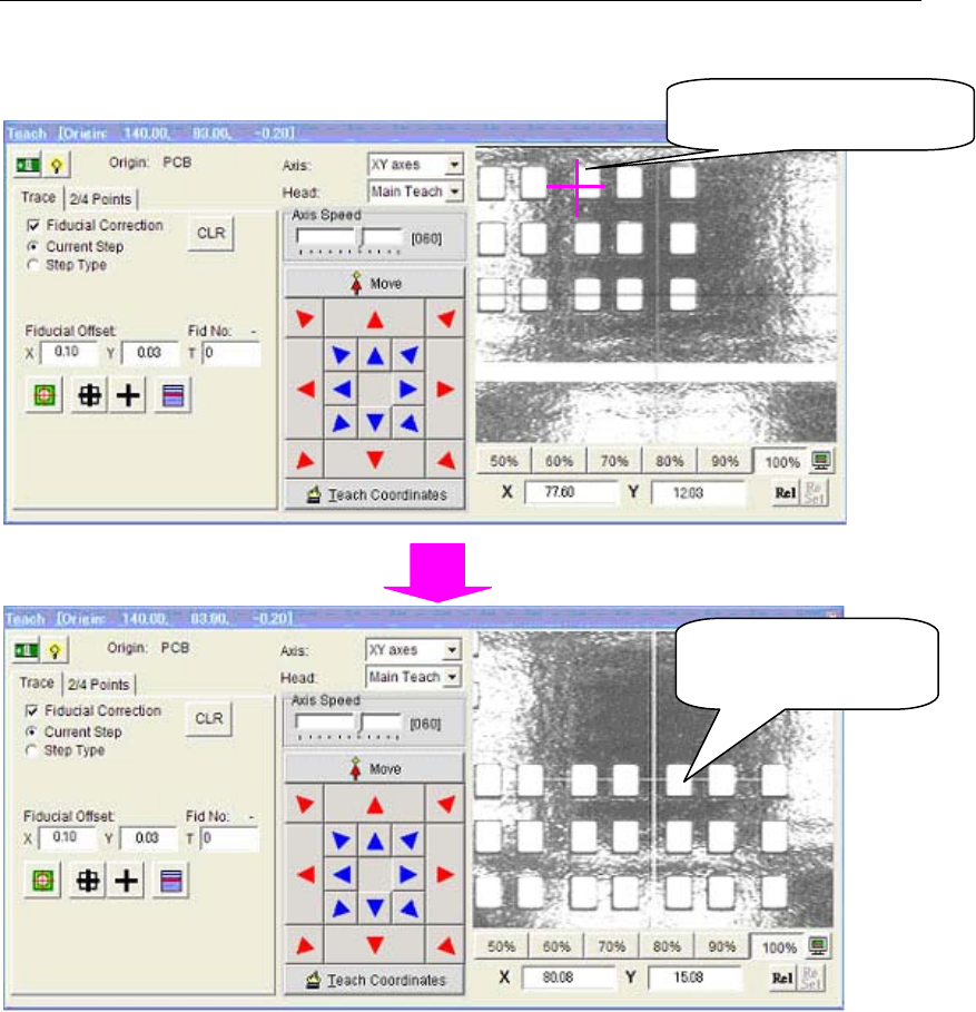
2-2-3 Click Move (Teach screen)
On the Teach Screen, when you double-click on any position of the Integrated Vision Window,
Teaching Camera immediately moves there so that the Camera center meets to the selected
position.
Teaching Camera has
just moved here.
When you double-click
here …
Chapter 2 Creating and Editing a Program
2-15
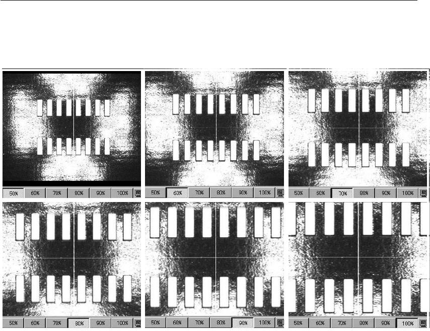
2-2-4 Switching Scaling of Integrated Vision Window (Teach Screen)
On the Teach Screen, Scaling of the Integrated Vision Window can be switched by 6 buttons from
50% to 100%. When 50% is selected, the field of view size of the Vision Window will be same as
that of the Teaching Camera. The bigger scaling, the smaller the field of view size is.
50% 60% 70%
80% 90% 100%