M20_Ope_E - 第68页
Chapter 2 Creating and Editing a Program 2-24 2-6 Entering Header and Editing Board Data 2-6-1 Header Menu: File>Header Type comment and editor name of the program for identification. Window: Comment: * Up to 40 chara…
Chapter 2 Creating and Editing a Program
2-23
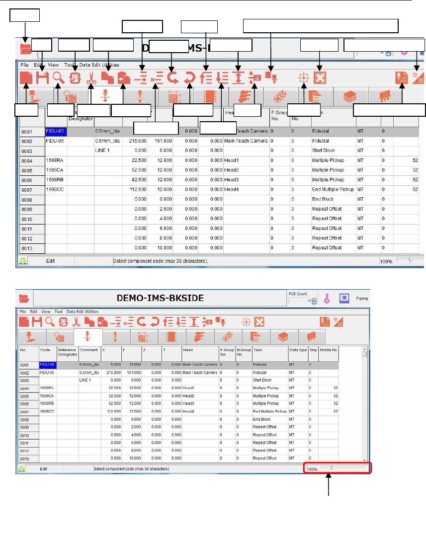
2-5-2 List of program data icons
Replace
Save
Ope
n
New Search
Cut
Copy Line
Paste Line
Insert Line
Delete Line
Bad Mark
Undo Edit
Redo Edit
Area Select
Clamp
Fiducial Data Auto Creatio
n
View (Simple/Detail)
First Line
Last Line
The window size
is zoomable with
the scroll bar.
Programmed Components & Nozzles
Chapter 2 Creating and Editing a Program
2-24
2-6 Entering Header and Editing Board Data
2-6-1 Header
Menu: File>Header
Type comment and editor name of the program for identification.
Window:
Comment: * Up to 40 characters can be entered.
Editor: * Up to 14 characters can be entered.
Note: Series Name, Version, and Unit are displayed for your information.
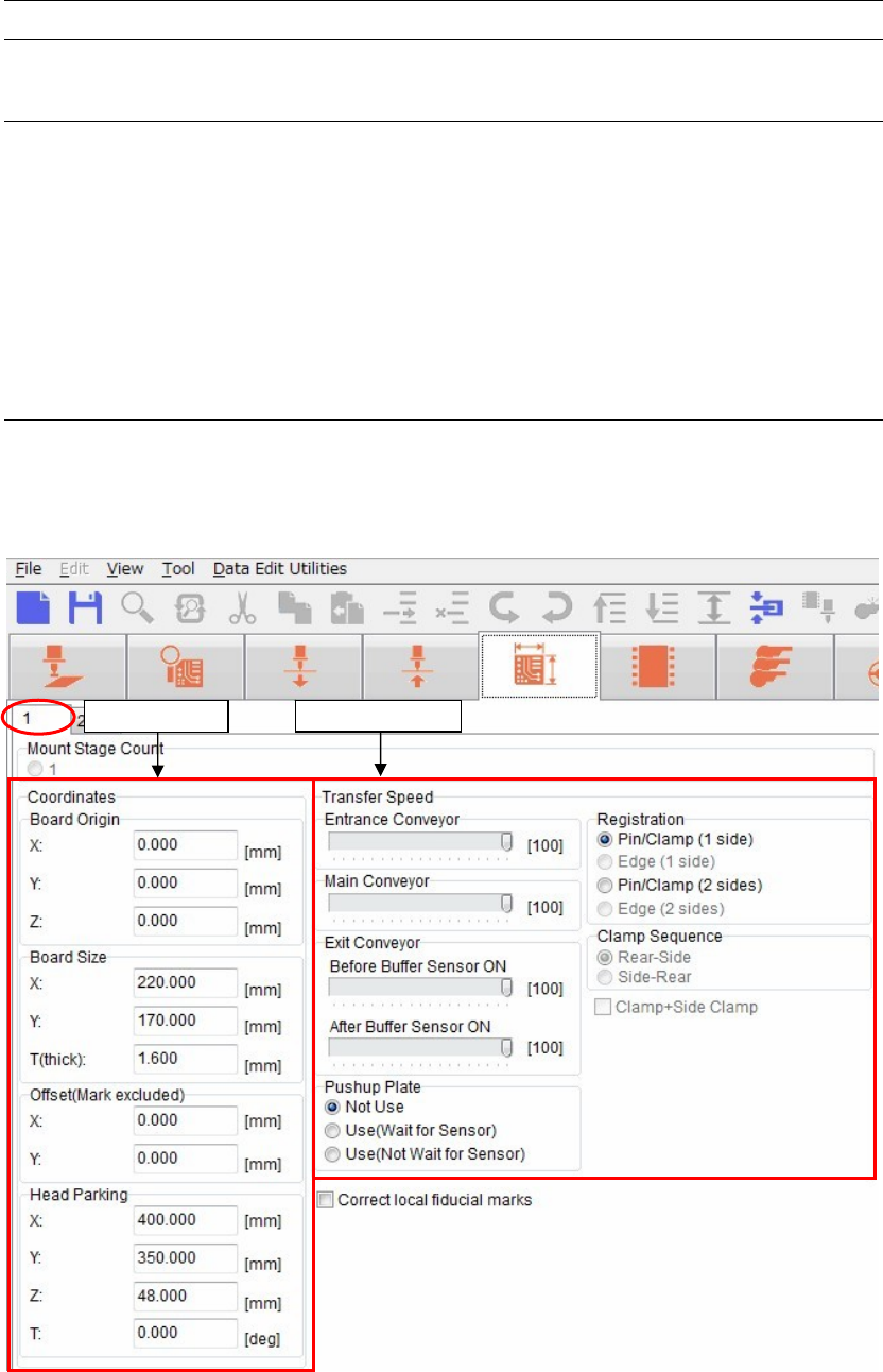
2-6-2 Entering board data
Menu: Board Data> Page 1
It is necessary to set the board data for each program.
Some settings must be set before setting a board.
Transfer S
p
eed
Coordinates
Chapter 2 Creating and Editing a Program
2-25
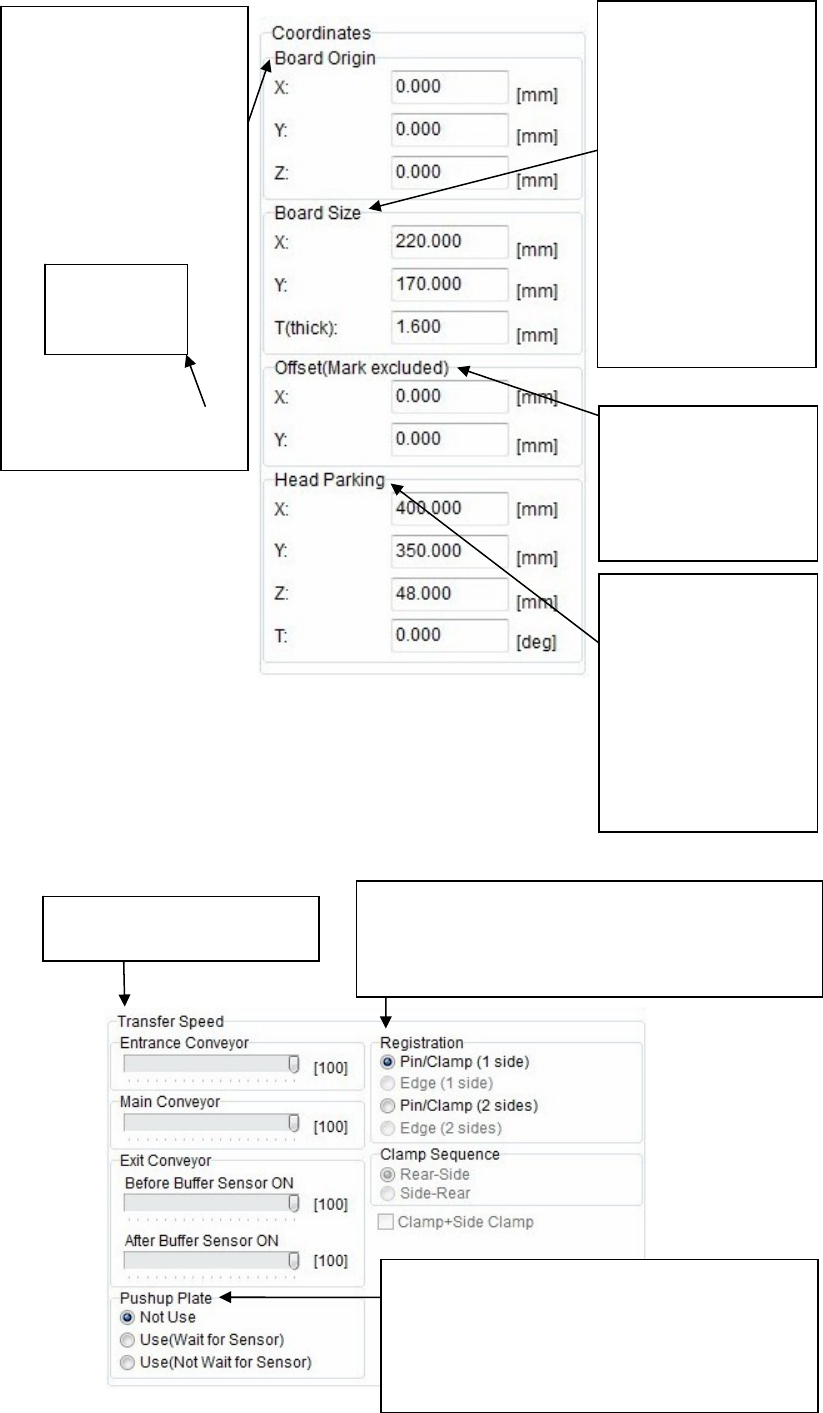
Coordinates
Transfer Speed
Enter a board size.
Enter a length in [X:]
and a width in [Y:].
In particular, be sure to
enter a width since it is
absolutely required for
the conveyor automatic
width adjustment.
Additionally, the height
of the board upper
surface may very
depending on the
thickness [T:]. So, enter
a thickness correct
value.
To correct the
placement results, enter
offset values.
All the placement
coordinates other than
the F mark can be offset.
Head parking position
can be set for each
program.
In addition to numeric
value entry,
double-clicking a box to
enter the coordinate of
relevant head parking
position through the
teaching.
Select a board securing method.
Select [Pin/Clamp (1 side)] for single-side placement
while select [Pin/Clamp (2 sides)] for double-side
placement.
Adjust the transfer speed of
each conveyor.
Set whether or not the pushup plate is used.
Additionally, when the pushup plate is used,
select to move to the next operation after the up
sensor of the pushup plate is turned ON or to
move to the next operation regardless of the
sensor ON operation.
The X/Y coordinates of the
board origin are the lower
right corner.
The Z coordinates are the
board upper surface.
These coordinates can be
changed.
To do so, enter offset values
based on the board origin
coordinates.
Board
X/Y coordinates of board
origin