M20_Ope_E - 第70页
Chapter 2 Creating and Editing a Program 2-26 Menu: Board Data> Page 2 Transfer Conditions The board loading timing and unloading timing can be adjusted. Transfer Conditions Height of pre-processed component Permiss…
Chapter 2 Creating and Editing a Program
2-25
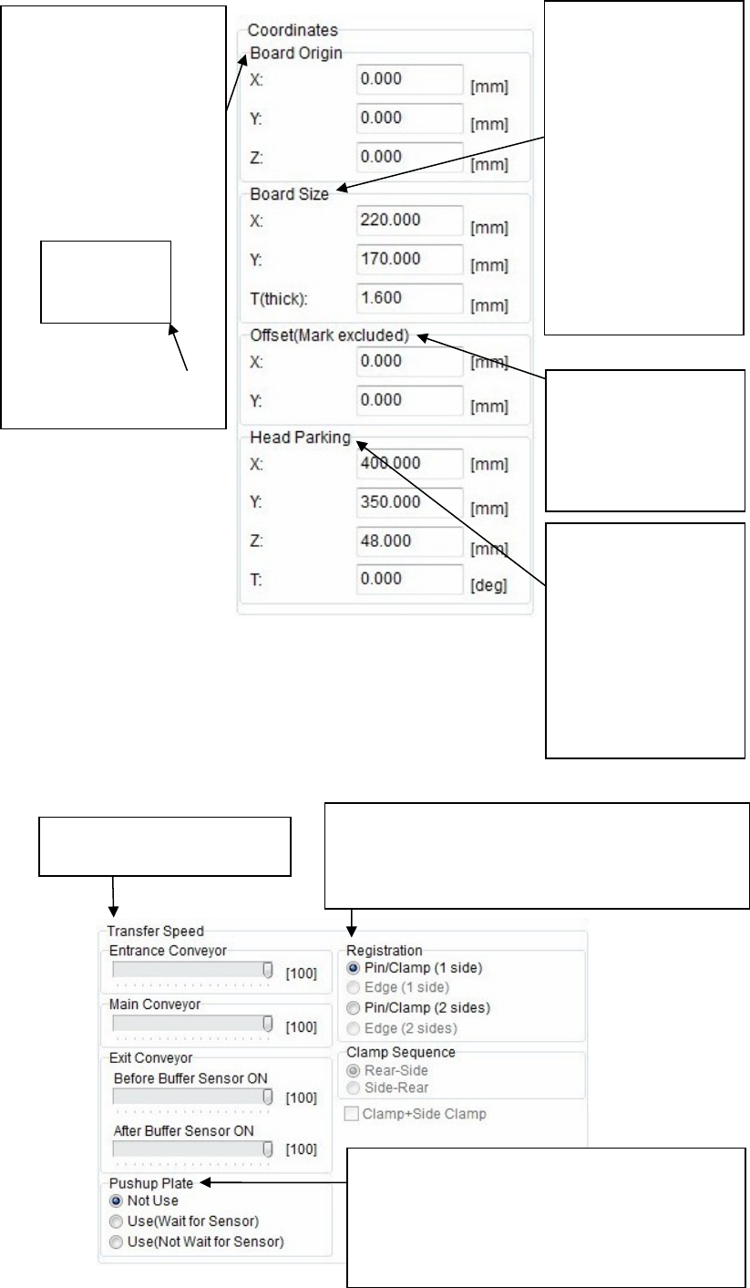
Coordinates
Transfer Speed
Enter a board size.
Enter a length in [X:]
and a width in [Y:].
In particular, be sure to
enter a width since it is
absolutely required for
the conveyor automatic
width adjustment.
Additionally, the height
of the board upper
surface may very
depending on the
thickness [T:]. So, enter
a thickness correct
value.
To correct the
placement results, enter
offset values.
All the placement
coordinates other than
the F mark can be offset.
Head parking position
can be set for each
program.
In addition to numeric
value entry,
double-clicking a box to
enter the coordinate of
relevant head parking
position through the
teaching.
Select a board securing method.
Select [Pin/Clamp (1 side)] for single-side placement
while select [Pin/Clamp (2 sides)] for double-side
placement.
Adjust the transfer speed of
each conveyor.
Set whether or not the pushup plate is used.
Additionally, when the pushup plate is used,
select to move to the next operation after the up
sensor of the pushup plate is turned ON or to
move to the next operation regardless of the
sensor ON operation.
The X/Y coordinates of the
board origin are the lower
right corner.
The Z coordinates are the
board upper surface.
These coordinates can be
changed.
To do so, enter offset values
based on the board origin
coordinates.
Board
X/Y coordinates of board
origin
Chapter 2 Creating and Editing a Program
2-26
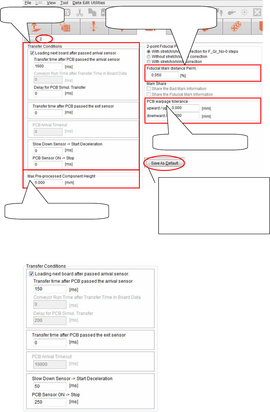
Menu: Board Data> Page 2
Transfer Conditions
The board loading timing and unloading timing can be adjusted.
Transfer Conditions
Height of pre-processed component
Permissible value of distance between
fiducial marks
PCB warpage tolerance value
<Save As Default> button
Saves the board data you have entered as
default values.
When clicking this button, the currently
set values become the default values that
are used when creating subsequent board
data newly.
Chapter 2 Creating and Editing a Program
2-27
① PCB Transfer Mode
Two kinds of PCB transfer modes are available as shown below.
Transfer mode PCB load timing
Normal transfer After a component-mounted PCB passes the conveyor exit sensor
Anticipate transfer After a component-mounted PCB passes the board arrival sensor
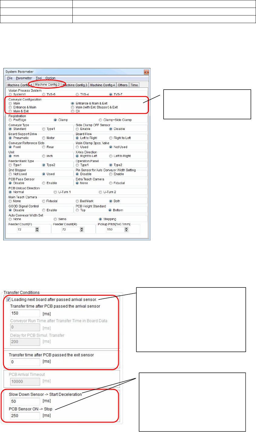
② Checking the conveyor configuration
Menu: System>SystemParameter>MachineConfig.2
You can check the conveyor configuration.
③ Setting the PCB transfer conditions
Change the transfer mode. Additionally, set a period of time for each item to adjust the transfer
timing.
Check the conveyor
configuration.
(You cannot change the data.)
When [Loading next board after passed
arrival sensor] is checked on, the
transfer mode enters the anticipate
transfer mode.
When this check box is checked off, the
transfer mode enters the normal
transfer mode.
Next, set a period of time for each item.
Adjust the conveyor deceleration start
timing in the [Slow Down Sensor ->
Start Deceleration] area.
Adjust the conveyor stop timing in the
[PCB Sensor ON -> Stop] area.
If the PCB does not reach the stopper,
increase the time.