M20_Ope_E - 第81页
Chapter 2 Creating and Editing a Program 2-37 How to Specify Bad Marks Bad mark functions are realized as follows: z PCB bad mark The PCB bad mark is used to determine whether the bad mark processes appearing after the…
Chapter 2 Creating and Editing a Program
2-36
2-7-1-3 Bad Mark Function
Menu: Program>Placement&MarkData>B_GroupNo.
General Description
The bad mark function permits the machine to cancel component placement if the machine
recognizes a bad mark affixed to the specified position on a PCB. Bad mark functions are classified
into three types.
z PCB bad mark function
Create a bad mark per PCB to determine whether the bad mark processes for the PCB will be
performed or not. When a PCB bad mark is not recognized, all the bad mark processes thereafter
are skipped, and therefore all the placements are executed.
z Block bad mark function
Create a bad mark per Block to determine whether component placements for a block (of
placement steps) will be performed or not. When a block bad mark is recognized, all the placement
steps within the block are skipped.
z Local bad mark function
Create a bad mark per placement step to determine whether a component will be placed or not.
When a local bad mark is recognized, the placement step for the component is skipped.
In placement program, bad mark functions stated above are realized with
“Master bad mark,” “Standard bad mark,” and “Group bad mark.”
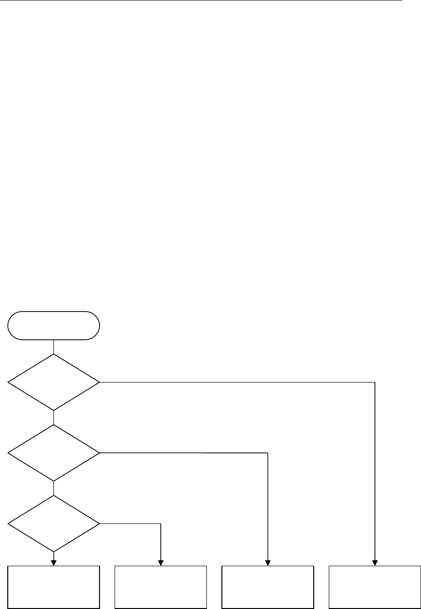
Bad Mark Logic
The logic for bad mark functions is shown below.
Note: There is a special Bad mark, other than PCB bad mark, Block bad mark, and Local bad mark. It is
called “PCB Select Bad mark”. For the detailed information to use it, refer to the description of
“PCB Select Bad mark”.
PCB bad mark is detected.
Block bad mark is detected.
Local bad mark is detected.
Bad Mark Logic
A placement step is
skipped.
A block of steps is
skipped.
All the placement
steps are executed.
Placement steps are
executed.
Yes
No
Yes
No
Yes
No
Chapter 2 Creating and Editing a Program
2-37
How to Specify Bad Marks
Bad mark functions are realized as follows:
z PCB bad mark
The PCB bad mark is used to determine whether the bad mark processes appearing after the mark
will be performed or not. Only when a PCB bad mark is recognized, the following bad mark
processes are performed.
The PCB bad mark is specified by the “Master bad mark.” The master bad mark is specified in the
first placement step. To specify a master bad mark, enter “255” in the [B Group No.] cell.
z Block bad mark
The block bad mark is used to determine whether component placements for a block (of placement
steps) will be performed or not. The block bad mark is specified by setting the “Standard bad
mark” right after the “Start Block Placement” step. To specify a standard bad mark, enter “0” in
the [B Group No.] cell.
z Local bad mark
The local bad mark is used to determine whether a component will be placed or not. The local bad
mark is specified by the “Group bad mark.” To specify a group bad mark, enter “1” to “249” in the
[B Group No.] cell.
Chapter 2 Creating and Editing a Program
2-38
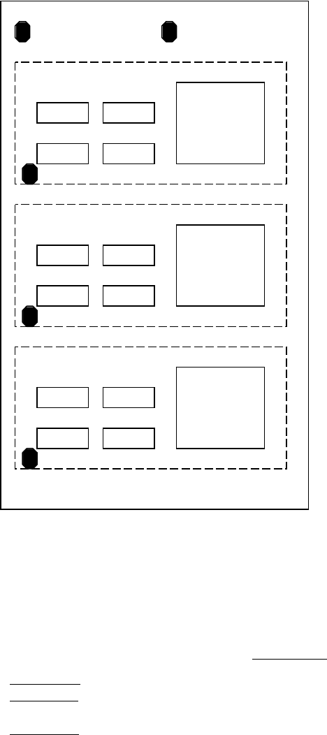
z Example
An example using the bad mark functions are shown below.
Bad mark A is used to determine if the bad mark processes will be performed or not.
Bad mark B is used to determine if the components C2 will be placed or not.
Bad mark X is used to determine if the placement steps for each block will be performed or not.
[Placement Program]
B Group No.
① Bad mark A
255 (PCB bad mark)
② Bad mark B
1 (Local bad mark)
③ Start of block placement
④ Bad mark X
0 (Block bad mark)
⑤ Placement of R1 (Multiple Pickup) 0
⑥ Placement of R2 (Multiple Pickup) 0
⑦ Placement of C1 (Multiple Pickup) 0
⑧ Placement of C2 (Multiple Pickup) 1 (determined by the local bad mark)
⑨ Placement of IC1 (Single Pickup) 0
⑩ End of block placement
⑪ Repeat offset 1 (Block 2)
⑫ Repeat offset 2 (Block 3)
R1
C1
R2
C2
IC1
Block 2
Bad Mark X
Bad Mark A
R1
C1
R2
C2
IC1
Block 1
Bad Mark X
R1
C1
R2
C2
IC1
Block 3
Bad Mark X
Bad Mark B