M20_Ope_E - 第96页
Chapter 2 Creating and Editing a Program 2-52 Smaller the component is, more critically the clea rance affects the pickup accuracy. Thus, for small chip components, we recommend to specify “0” as simultaneous pickup perm…

Chapter 2 Creating and Editing a Program
2-51
2-7-1-7 7Multiple/Simultaneous Pickup
Menu: Program>Placement&MarkData>Task>MultiplePickup
Program>Placement&MarkData>Task>SinglePickup
There are three ways the head assembly picks up a component or components:
Single Pickup
A head moves to a pickup point for a component and transports it to a placement point. Although
this is the slowest method, it must be employed depending on the size and the number of
programmed components.
Multiple Pickup
Two or more heads move to one or more pickup points. Each head picks up a component at
different timings.
Simultaneous Pickup
Two or more heads move to pickup points at the same timing—the fastest of the three methods.
You can approach the maximum tact time by simultaneous pickup with 4 or 6 heads.
To allow simultaneous pickup to occur...
● “Multiple Pickup” is specified to [Task] of the placement data.
● Component size is 1005 or larger.
● Feeders are placed at the same spacing as the heads. (Each feeder can have
tolerance, which is specified for Component Library. See below.)
Example: Perform simultaneous pickup using Head 1 and 2 at feeders located at 30mm spacing.
Simultaneous pickup permissions for the components are 0.2mm and 0.1mm.
Tape feeder
Tape feeder
Head 2 Head 1
0.1 0.1 0.2 0.2
Feeder pitch X
In the above example, simultaneous pickup is possible when the feeder pitch is within the range
from (Feeder pitch X + 0.3) to (Feeder pitch X - 0.3).
Define the simultaneous pickup permission keeping in mind a component is stored in a tape
cavity with clearance.
Clearance between the component and the
tape cavity disables component pickup at
the component center.
Chapter 2 Creating and Editing a Program
2-52
Smaller the component is, more critically the clearance affects the pickup accuracy. Thus, for small
chip components, we recommend to specify “0” as simultaneous pickup permission (default:
0.1mm), and for larger components, specify larger value as far as the simultaneous pickup is
successfully performed. This way the risk of simultaneous pickup failure for small chip
components is minimized: when the requirements for simultaneous pickup are not met,
continuous pickup substitutes for ensuring reliable operation.
Retrial for Simultaneous Pickup of the Same Component
As shown in the below program, when a retrial for the multiple pickup of the same component
occurs, all the assigned heads pick up components from the same pickup point that is entered
earliest of all the assigned pickup data. (No. 005 of the pickup data in the below example).
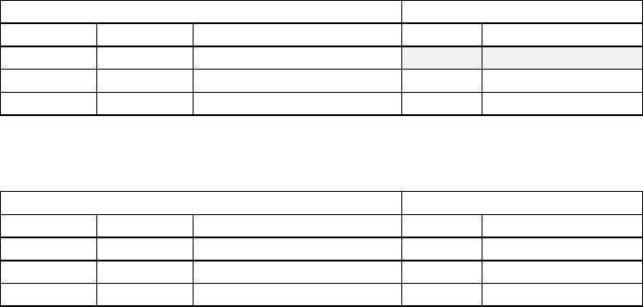
Placement & Mark Data Pickup Data
Code Head Task No. Component Code
R1608 Head1 Multiple Pickup
005 R1608
R1608 Head2 Multiple Pickup 006 R1608
R1608 Head3 End Multiple Pickup 007 R1608
To let each assigned head pick up at different pickup point in case of a retrial, enter different code
for the same component as shown below.
Placement & Mark Data Pickup Data
Code Head Task No. Component Code
R1608A Head1 Multiple Pickup 005 R1608A
R1608B Head2 Multiple Pickup 006 R1608B
R1608C Head3 End Multiple Pickup 007 R1608C
Chapter 2 Creating and Editing a Program
2-53
2-7-1-8 Rotated Multi-Panel PCB
Menu: Program>Placement&MarkData>Task>StartBlock
Program>Placement&MarkData>Task>EndBlock
Program>Placement&MarkData>Task>RepeatOffset
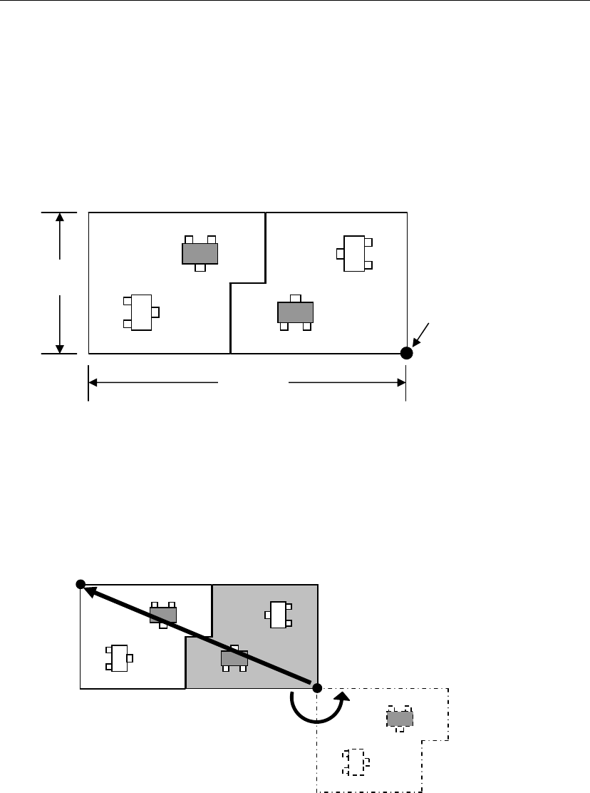
If a PCB consists of panels rotated at different angles (e.g. PCB shown below), PCB data must be
created as explained below using the repeat offset.
This section explains how to create data that uses the panel located at the PCB origin as the
reference. First, edit normal repeat placement data based on the placement data of the reference
panel (gray area). Next, specify the position and orientation of the other panel (the panel that is
reversed diagonally) using the repeat offset values.
■ Obtaining the Offset Values
① Rotate the reference panel (gray panel) around the PCB origin until it is in the same
orientation as the other panel, and set the rotated angle to the θ coordinate.
② Shift the rotated panel in X and Y directions up to the actual offset, and then set the shift
values to the X and Y coordinates.
200mm
80mm
PCB origin
X coordinate = 200.0
Y coordinate = 80.00
θcoordinate = 180.00