M20_Ope_E - 第97页
Chapter 2 Creating and Editing a Program 2-53 2-7-1-8 Rotated Multi-Panel PCB Menu: Program>Placement&MarkData>Task>StartBlock Program>Placement&M arkData>Task>EndBlock Program>Placement&…
Chapter 2 Creating and Editing a Program
2-52
Smaller the component is, more critically the clearance affects the pickup accuracy. Thus, for small
chip components, we recommend to specify “0” as simultaneous pickup permission (default:
0.1mm), and for larger components, specify larger value as far as the simultaneous pickup is
successfully performed. This way the risk of simultaneous pickup failure for small chip
components is minimized: when the requirements for simultaneous pickup are not met,
continuous pickup substitutes for ensuring reliable operation.
Retrial for Simultaneous Pickup of the Same Component
As shown in the below program, when a retrial for the multiple pickup of the same component
occurs, all the assigned heads pick up components from the same pickup point that is entered
earliest of all the assigned pickup data. (No. 005 of the pickup data in the below example).
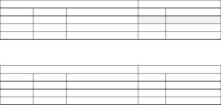
Placement & Mark Data Pickup Data
Code Head Task No. Component Code
R1608 Head1 Multiple Pickup
005 R1608
R1608 Head2 Multiple Pickup 006 R1608
R1608 Head3 End Multiple Pickup 007 R1608
To let each assigned head pick up at different pickup point in case of a retrial, enter different code
for the same component as shown below.
Placement & Mark Data Pickup Data
Code Head Task No. Component Code
R1608A Head1 Multiple Pickup 005 R1608A
R1608B Head2 Multiple Pickup 006 R1608B
R1608C Head3 End Multiple Pickup 007 R1608C
Chapter 2 Creating and Editing a Program
2-53
2-7-1-8 Rotated Multi-Panel PCB
Menu: Program>Placement&MarkData>Task>StartBlock
Program>Placement&MarkData>Task>EndBlock
Program>Placement&MarkData>Task>RepeatOffset
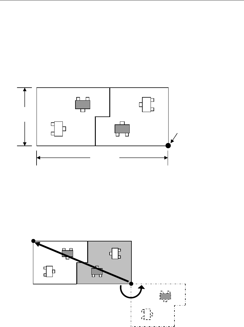
If a PCB consists of panels rotated at different angles (e.g. PCB shown below), PCB data must be
created as explained below using the repeat offset.
This section explains how to create data that uses the panel located at the PCB origin as the
reference. First, edit normal repeat placement data based on the placement data of the reference
panel (gray area). Next, specify the position and orientation of the other panel (the panel that is
reversed diagonally) using the repeat offset values.
■ Obtaining the Offset Values
① Rotate the reference panel (gray panel) around the PCB origin until it is in the same
orientation as the other panel, and set the rotated angle to the θ coordinate.
② Shift the rotated panel in X and Y directions up to the actual offset, and then set the shift
values to the X and Y coordinates.
200mm
80mm
PCB origin
X coordinate = 200.0
Y coordinate = 80.00
θcoordinate = 180.00

Chapter 2 Creating and Editing a Program
2-54
2-7-2 Pickup Data
Menu: PickupData
In simple display mode, items “X”, “Y”, “Z”, “θ” and “Shortage Alarm” can be hidden.
Item:
Component code Enter the component code. (Linked to the placement & mark data and
component libraries)
Specify the pickup-point information for this component. If there are
component codes that have been registered, the desired component
code can be selected from the combo box that appears when a
right-click is made.
★Up to 38 characters can be entered.
X, Y, Z Offset If necessary, set the X, Y and Z offset values for the pickup coordinates
that are registered prior to shipment of the mounter. When teaching of
a pickup-point is performed and its coordinates are determined, the
offset values will be entered for these items automatically. (To do this,
locate the cursor on a pickup-point under [ST No.], and select Tool >
Teach or right-click on one of the offset cells.) To use this function,
entries in [Feed Style] and [ST No.] must be made in advance.
★Unit: 0.01mm
θ Offset Set the offset value for the θ pickup coordinates that are registered
prior to shipment of the mounter.
★Unit: 0.01°
Feed Style Right-click in a [Feed Style] cell. A pop-up menu will appear, so select
the feeder location (feeder style) from which components are to be
picked up. The feeder location can be selected from ST-F (front station),
ST-R (rear station), and CTF (changeable tray feeder).
ST No. If ST-F/R is selected for “Feed Style”, select the desired pickup-point
No. (ST No.) Feeder station Nos. are shown on the mounter: they are
numbered from No.1 to No. 36 from right to left when viewed from the
front side, and No.1 to No. 36 from left to right when viewed from the
rear side. CTF (changeable tray feeder) is selected, specify any number
(1 to 199) for distinguishing purposes, however, the same ST No.
cannot be used twice in the same program.
In the case of PS-MS3, nine different feeder names (PS-MS3-A to –I) are
available, however, the ST No. for which MS3 is set will be used for
each of those feeders.
9 kinds of feeder names from PS-MS3-A to PS-MS3-I can be set for the
PS-MS3 multi-stick feeder. However, different feeder names share the
same station number (where electrical contact between the feeder bank
and PS-MS3 is made).
Accordingly, 16 kinds of feeder names from MSF-01 to MSF-16 can be
set for the MSF-1 multi-stick feeder. However, different feeder names
share the same station number (where electrical contact between the
feeder bank and MSF-1 is made).
Feeder / Pallet If ST-F/R is selected for “Feed Style”, select the desired feeder name
from the combo box that appears when a right-click is made. (Linked
with feeder names registered in the feeder library.) If a feed style other
than ST-F/R is selected, select the desired pallet name from the combo
box that appears when a right-click is made. (Linked with pallet names
registered in the pallet library.) If you want to use a new pallet name,
enter it manually to create it in the pallet library. For multi-stick feeder
names, refer to “Feeder Library” in “4. Libraries”.
Packaging / Tray If ST-F/R is selected for “Feed Style”, select the desired packaging
name from the combo box that appears when a right-click is made.
(Linked with packaging names registered in the packaging library.)
If a feed style other than ST-F/R is selected, select the desired tray
name from the combo box that appears when a right-click is made.
(Linked with tray names registered in the tray library.)
If you want to use a new packaging/tray name, enter it manually to
create it in the packaging/tray library.
Availability Select “Available” or “Not Available”.