MDO3000 Programmer Manual.pdf - 第19页
Getting Started T able 1-1: Updates to the MDO3000 and MD O4000C Series Oscilloscopes (cont.) Feature Use these comm ands Additional RF Spectrogram and Spectrum Trace commands RF:SPECTRogram RF:SPECTRogram:SLICETIMe? RF:…

Getting Started
Table 1-1: Updates to the MDO3000 and MDO4000C Series Oscilloscopes (cont.)
Feature Use these comm ands
Video Picture functionality (standard on MDO3000). R equires
the D PO4VID application module for use with MSO/DPO4000B
and MDO4000/B/C models)
VIDPic:AUTOContrast
VIDPic:AUTOContrast:UPDATERate
VIDPic:BRIGHTNess
VIDPic:CONTRast
VIDPic:DISplay
VIDPic:FRAMETYPe
VIDPic:LOCation:HEIght
VIDPic:LOCation:OFFSet
VIDPic:LOCation:STARt:LINE
VIDPic:LOCation:STARt:PIXel
VIDPic:LOCation:WIDth
VIDPic:LOCation:X
VIDPic:LOCation:Y
VIDPic:SOUrce
VIDPic:STANdard
Dual edge trigger/search functionality TRIGger:A:EDGE:SLOpe
SEARCH:SEARCH<x>:TRIGger:A:EDGE:SLOpe
FastAcq™ high-speed waveform acquisition mode
New color palettes (Temperature, Spectral, Normal, Inverted)
ACQuire:FASTAcq:STATE
ACQuire:FASTAcq:PALEtte
Digital C hannel Activity Monitor DISplay:DIGital:ACTIVity
Additional calibration status queries
CALibrate:INTERNal:STATus:RF?
CALibrate:INTERNal:STATus:SCOPE?
CALibrate:RESults:FACtory:AFG ?
CALibrate:RESults:FACtory:RF?
CALibrate:RESults:FACtory:SCOPE?
CALibrate:RESults:SPC:RF?
CALibrate:RESults:SPC:SCOPE?
Additional configuration queries
(AFG, ARB, DVM, and VidPic are available for MDO 3000 and
MDO4000C series. VidPic requires the DPO4VID application
module on the MSO/DPO4000B and MDO4000/B/C models)
CONFIGuration:AFG?
CONFIGuration:APPLications:CUSTOMMask?
CONFIGuration:APPLications:STANDARDMask?
CONFIGuration:APPLications:VIDPIC?
CONFIGuration:ARB?
CONFIGuration:DVM?
Math vertical autoscale feature MATH[1]:AUTOSCale
Total overshoot measurement type
MEASUrement:IMMed:TYPe
MEASUrement:MEAS<x>:TYPe
1-6 MDO4000/B/C, MSO/DPO4000B and MDO3000 Series Oscilloscopes Programmer Manual

Getting Started
Table 1-1: Updates to the MDO3000 and MDO4000C Series Oscilloscopes (cont.)
Feature Use these comm ands
Additional RF Spectrogram and Spectrum Trace commands RF:SPECTRogram
RF:SPECTRogram:SLICETIMe?
RF:SPECTRogram:TIMe?
RF:SPECTRUMTrace
Ability to save RF baseband I & Q data to a M atlab level 5
file or .TIQ file
SAVe:WAVEform:FILE Format:RF_BB_IQ
Table 1-2: Updates to the MDO3000 and MDO4000C Series Oscilloscopes
Feature Use these commands
System reboot REBOOT
CANFDbusconfiguration CONFIGuration:BUSWAVEFORMS:CANFD?
BUS:B<x>:CAN:FD:STANDard
BUS:B<
x>:CAN:FD:BITRate
BUS:B<x>:CAN:STANDard
BUS:B<x>:DISplay:FORMat
Can F D search criteria SEARCH:SEARCH<x>:TRIGger:A:BUS:B<x>:CAN:CONDition
SEARC
H:SEARCH<x>:TRIGger:A:BUS:B<x>:CAN:DATa:OFFSet
SEARCH:SEARCH<x>:TRIGger:A:BUS:B<x>:CAN:FD:BRSBIT
SEARCH:SEARC H<x >:T R IGger:A:BUS:B<x>:CAN:FD:ESIBIT
CAN FD trigger TRIGger:A:BUS :B<x>:CAN:CONDition
TRI
Gger:A:BUS:B<x>:CAN:D ATa:OFFSet
TRIGger:A:BUS :B<x>:CAN:FD:BRSBIT
TRIGger:A:BUS :B<x>:CAN:FD:ESIBIT
SettingUpRemoteCommunicationsHardware
Yo
u can remotely control communications between your oscilloscope and a PC
via Ethernet, USB, or GPIB cables.
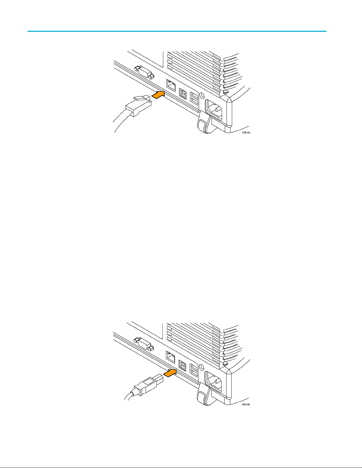
Ethernet
If you are using Ethernet, start by connecting an appropriate Ethernet cable to the
Ethernet port (RJ-45 connector) on the rear panel of your oscilloscope. This
connects the oscilloscope to a 10BASE-T/100BASE-TX/1000BASE-T local area
network.
MDO4000/B/C, MSO/DPO4000B and MDO3000 Series Oscilloscopes Programmer Manual 1-7
Getting Started
To change the Ethernet settings on your oscilloscope, do the following:
1. On the front panel, push Utility.
2. Push Utility Page.
3. Select I/O with the Multipurpose knob.
4. Push Network Configuration.
5. On the side menu, if you are on a DHCP Ethernet network and using a through
cable, push Automatic (DHCP & Auto-IP).
6. If you are using a cross-over cable, push Manual, and press Set IP Addresses
Manually to set a hard coded TCP/IP address.
USB
If you are using USB, start by connecting the appropriate USB cable to the USB
2.0 high-speed (HS) device port on the rear panel of your oscilloscope. This
port requires that the cable connected from the port to the host computer meets
the USB 2.0 specification for high speed connections. Typically, such cables
should be 3 feet or shorter in length, but this is determined by the quality ofthe
cable and, with higher quality cables, this length can be extended. (It is also
dependent upon the drive capability of the host USB port to which the instrument
is connected.) The use of high quality short cables is recommended to avoid USB
connection problems.
1-8 MDO4000/B/C, MSO/DPO4000B and MDO3000 Series Oscilloscopes Programmer Manual