MDO3000 Programmer Manual.pdf - 第21页
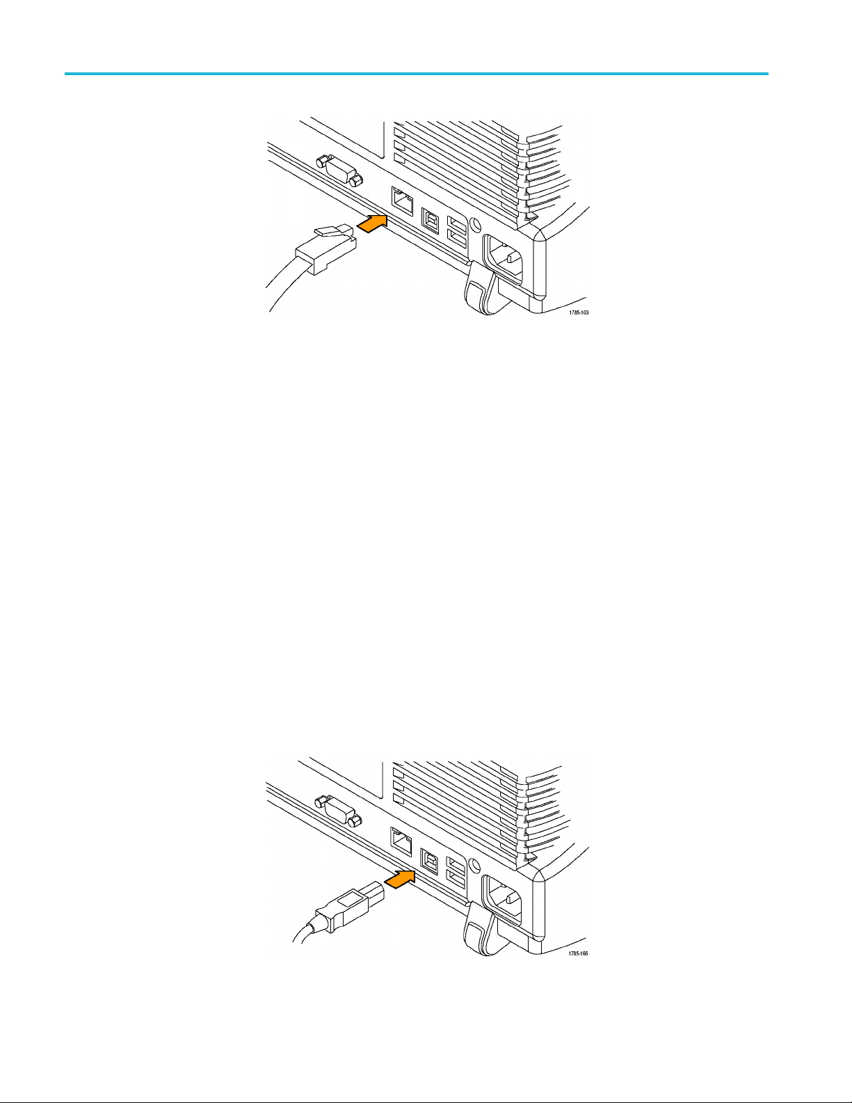
Getting Started W ith USB, the sy stem automatically configures itself. T o verify that the USB is enabled: 1. On the front pa nel, push Utility . 2. Push Utility Page . 3. Select I/O with the Multipurpose knob. 4. Push U…
Getting Started
To change the Ethernet settings on your oscilloscope, do the following:
1. On the front panel, push Utility.
2. Push Utility Page.
3. Select I/O with the Multipurpose knob.
4. Push Network Configuration.
5. On the side menu, if you are on a DHCP Ethernet network and using a through
cable, push Automatic (DHCP & Auto-IP).
6. If you are using a cross-over cable, push Manual, and press Set IP Addresses
Manually to set a hard coded TCP/IP address.
USB
If you are using USB, start by connecting the appropriate USB cable to the USB
2.0 high-speed (HS) device port on the rear panel of your oscilloscope. This
port requires that the cable connected from the port to the host computer meets
the USB 2.0 specification for high speed connections. Typically, such cables
should be 3 feet or shorter in length, but this is determined by the quality ofthe
cable and, with higher quality cables, this length can be extended. (It is also
dependent upon the drive capability of the host USB port to which the instrument
is connected.) The use of high quality short cables is recommended to avoid USB
connection problems.
1-8 MDO4000/B/C, MSO/DPO4000B and MDO3000 Series Oscilloscopes Programmer Manual

Getting Started
With USB, the sy
stem automatically configures itself. To verify that the USB is
enabled:
1. On the front pa
nel, push Utility.
2. Push Utility Page.
3. Select I/O with the Multipurpose knob.
4. Push USB, and verify that USB is enabled.
5. If USB is disabled, push Connect to Computer on the side menu.
After connection, the host, with appropriate software, can list the oscilloscope as a
USB device with the following parameters: (See Table 1-3.)
Table 1-3: USB Device Parameters
Parameter Value
Manufacturer ID 0x0699 (decimal 1689)
Product ID
The product id varies by model number as
follows:
(You can send the
USBTMC:PRODUCTID:HEXadecimal?
query to read the value)
DPO4104B 0x0405 (decimal 1029)
DPO4054B 0x0406 (decimal 1030)
DPO4034B 0x0407 (decimal 1031)
MSO4104B 0x0409 (decimal 1033)
MSO4054B 0x040A (decimal 1034)
MSO4034B 0x040B (decimal 1035)
MDO4104-6 0x040C (decimal 1036)
MDO4104-3 0x040D (decimal 1037)
MDO4054-6 0x040E (decimal 1038)
MDO4054-3 0x040F (decimal 1039)
DPO4102B 0x0417 (decimal 1047)
DPO4102B-L 0x0418 (decimal 1048)
DPO4104B-L 0x0419 (decimal 1049)
MSO4102B 0x041A (decimal 1050)
MSO4102B-L 0x041B (decimal 1051)
MSO4104B-L 0x041C (decimal 1052)
DPO4014B 0x0426 (decimal 1062)
MSO4014B 0x0428 (decimal 1064)
MDO4014-3 0x042a (decimal 1066)
MDO4034-3 0x042e (decimal 1070)
MDO3000 (all) 0x408 (decimal 1032)
MDO4000C (all) 0x0456 (decimal 1110)
Serial number Serial number
Manufacturer description
“Tektronix”
Interface description “USBTMC-USB488”
MDO4000/B/C, MSO/DPO4000B and MDO3000 Series Oscilloscopes Programmer Manual 1-9
Getting Started
GPIB
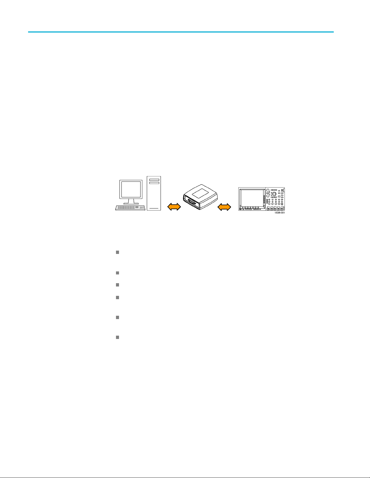
To use GPIB (Gen
eral Purpose Interface Bus), start by connecting an appropriate
USB cable to the USB 2.0 high-speed (HS) device port on the rear panel of your
oscilloscope. Connect the other end to the TEK-USB-488 Adapter host port. Then
connect a GPIB cable from the TEK-USB-488 Adapter to your PC.
Supply power to the Adapter in either of these two ways:
1. Use the optional 5 V
DC
power adapter connected to the 5 V
DC
power input
on the Adapter.
2. Use an appropriate USB cable connected to a powered USB host port on your
PC and the Device port on the TEK-USB-488 Adapter.
The oscilloscope has a USB 2.0 high-speed (HS) device port to control the
oscilloscope through USBTMC or GPIB with a TEK-USB-488 Adapter. The
USBTMC protocol allows USB devices to communicate using IEEE488 style
messages. This lets you run your GPIB software applications on USB hardware.
Before setting up the oscilloscope for remote communication using the electronic
(physical) GPIB interface, you should familiarize yourself with the following
GPIB requirements:
A unique device address must be assigned to each device on the bus. No two
devices can share the same device address.
No more than 15 devices can be connected to any one line.
One device should be connected for every 6 feet (2 meters) of cable used.
No more than 65 feet (20 meters) of cable should be used to connect devices
to a bus.
At least two-thirds of the devices on the network should be powered on while
using the network.
Connect the devices on the network in a star or linear configuration. Do not
use loop or parallel configurations.
To function correctly, your oscilloscope must have a unique device address. The
default setting for the GPIB configuration is GPIB Address 1.
1-10 MDO4000/B/C, MSO/DPO4000B and MDO3000 Series Oscilloscopes Programmer Manual