MDO3000 Programmer Manual.pdf - 第23页
Getting Started To c h a n g e t h e G P IB address settings, do the following: 1. On the front panel, push Utility . 2. Push Utility Page . 3. Select I/O with the Multipurpose knob. 4. Push GPIB . 5. Enter the GPIB addr…
Getting Started
GPIB
To use GPIB (Gen
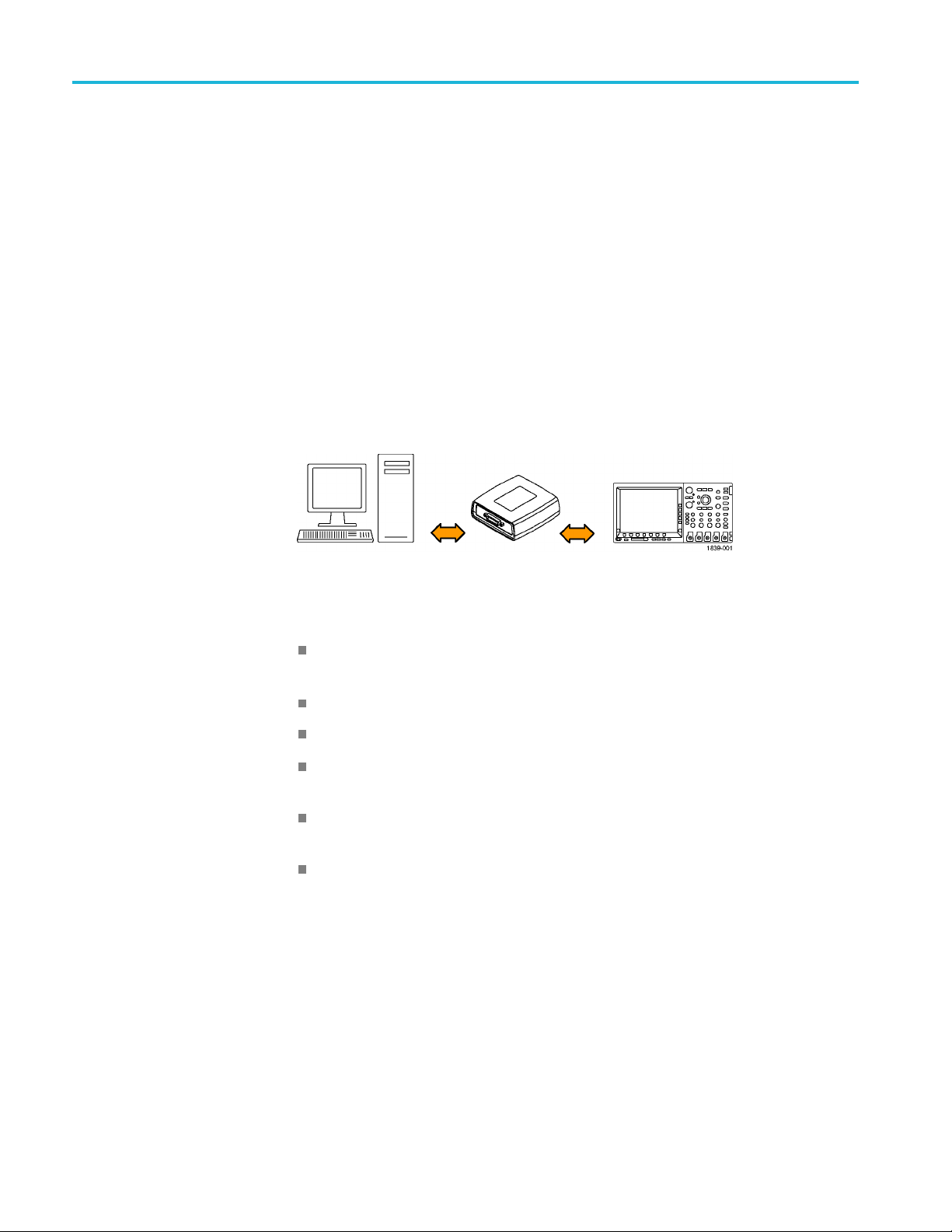
eral Purpose Interface Bus), start by connecting an appropriate
USB cable to the USB 2.0 high-speed (HS) device port on the rear panel of your
oscilloscope. Connect the other end to the TEK-USB-488 Adapter host port. Then
connect a GPIB cable from the TEK-USB-488 Adapter to your PC.
Supply power to the Adapter in either of these two ways:
1. Use the optional 5 V
DC
power adapter connected to the 5 V
DC
power input
on the Adapter.
2. Use an appropriate USB cable connected to a powered USB host port on your
PC and the Device port on the TEK-USB-488 Adapter.
The oscilloscope has a USB 2.0 high-speed (HS) device port to control the
oscilloscope through USBTMC or GPIB with a TEK-USB-488 Adapter. The
USBTMC protocol allows USB devices to communicate using IEEE488 style
messages. This lets you run your GPIB software applications on USB hardware.
Before setting up the oscilloscope for remote communication using the electronic
(physical) GPIB interface, you should familiarize yourself with the following
GPIB requirements:
A unique device address must be assigned to each device on the bus. No two
devices can share the same device address.
No more than 15 devices can be connected to any one line.
One device should be connected for every 6 feet (2 meters) of cable used.
No more than 65 feet (20 meters) of cable should be used to connect devices
to a bus.
At least two-thirds of the devices on the network should be powered on while
using the network.
Connect the devices on the network in a star or linear configuration. Do not
use loop or parallel configurations.
To function correctly, your oscilloscope must have a unique device address. The
default setting for the GPIB configuration is GPIB Address 1.
1-10 MDO4000/B/C, MSO/DPO4000B and MDO3000 Series Oscilloscopes Programmer Manual

Getting Started
To change the GP
IB address settings, do the following:
1. On the front panel, push Utility.
2. Push Utility Page.
3. Select I/O with the Multipurpose knob.
4. Push GPIB.
5. Enter the GPIB address on the side menu, using the multipurpose knob. This
will set the GPIB address on an attached TEK-USB-488 Adapter.
The oscilloscope is now set up for bidirectional communication with your
controller.
Setting Up Remote Communications Software
Connect your oscilloscope directly to a computer to let the PC analyze your data,
collect screen images, or to control the oscilloscope using a program of your own
creation. Three ways to connect your oscilloscope to a computer are throughthe
VISA drivers, the e*Scope Web-enabled tools, or via a socket server.
Using
VISA
VISA lets you use your MS-Windows computer to acquire data from your
oscilloscope for use in an analysis package that runs on your PC, such as
Microsoft Excel, National Instruments LabVIEW, Tektronix OpenChoice Desktop
soft
ware, or your own custom software. You can use a common communications
connection, such as USB, Ethernet, or GPIB, to connect the computer to the
oscilloscope.
To set up VISA communications between your oscilloscope and a computer:
MDO4000/B/C, MSO/DPO4000B and MDO3000 Series Oscilloscopes Programmer Manual 1-11

Getting Started
1. Load the VISA dr
ivers on your computer. Also, load your application, such
as OpenChoice Desktop. You will find the drivers and OpenChoice Desktop
software on the appropriate CD that comes with your oscilloscope or at the
Tektronix software finder Web page (www.tektronix.com\downloads).
2. Connect the oscilloscope to your computer with the appropriate USB or
Ethernet cable. To communicate between the oscilloscope and a GPIB system,
connect the oscilloscope to the TEK-USB-488 GPIB-to-USB Adapter with
a USB cable. Then connect the adapter to your GPIB system with a GPIB
cable. Cyc
le the power on the oscilloscope.
3. Push Utility.
4. Push Utility Page.
5. Turn multipurpose knob a and select I/O.
6. If you are using USB, the system sets itself up automatically for you, if USB is
enabled. Check USB on the lower menu to be sure that USB is enabled. If it is
not enabled, push USB. Then push Connect to Computer on the side menu.
7. To use Ethernet, push Ethernet & LXI on the lower menu. Use the side menu
buttons to adjust your network settings, as needed. For more information, see
the e*Scope setup information below.
8. If you want to change socket server parameters, push Socket Server and enter
new values through the resulting side menu.
9. If you are using GPIB, push GPIB. Enter the GPIB address on the side menu,
using multipurpose knob a. This will set the GPIB address on an attached
TEK
-USB-488 Adapter.
10. Run your application software on your computer.
Qu
ick Tips
Your oscilloscope shipped with a CD containing a variety of Windows-based
software tools for efficient connectivity between your oscilloscope and your
computer. These include toolbars that speed connectivity with Microsoft
E
xcel and Word. There are also two standalone acquisition programs called
NI LabVIEW SignalExpress™, Tektronix Edition and Tektronix OpenChoice
Desktop.
The rear-panel USB 2.0 high-speed (HS) device port is the correct USB port
for computer connectivity. Use the rear- and front-panel USB 2.0 host ports
to connect your oscilloscope to USB flash drives, hard drives, printers and
keyboards. Use the USB Device port to connect your oscilloscope to a PC or
a PictBridge printer.
1-12 MDO4000/B/C, MSO/DPO4000B and MDO3000 Series Oscilloscopes Programmer Manual