IPC-4556 印制板化学镍钯浸金(ENEPIG)规范ENG.pdf - 第15页
3.1 Visual ENEPIG surfaces shall be inspected in accor- dance with the visual examination sections of the IPC-6010 series specifications, specifically IPC-6012 which specifies the use of a nominal magnification of 1.75X (app…
2.7 Terms, Definitions and Acronyms The definition of all terms used herein shall be as specified in IPC-T-50 and as
defined below:
MTO (Metal Turnover) – A measure of electroless or immersion plating bath ‘‘age,’’ MTO is a period of operation during
which the sum of the periodic replenishments of the metal being deposited is equal to the amount of metal in the initial bath
makeup. For example, if the metal concentration in an electroless bath is 5 grams per liter and the bath is 100 liters in size,
then one MTO is the period of useage during which 500 grams of metal is added back into the bath by replenishment as the
metal is actively being deposited out of the bath. Depending on how heavily an electroless or immersion bath is being
‘worked’, the time taken for one MTO may range from as little as a few hours to a week or more. It is common for an
electroless or immersion plating bath to last for multiple MTOs before being removed from service and fully replaced.
3 REQUIREMENTS
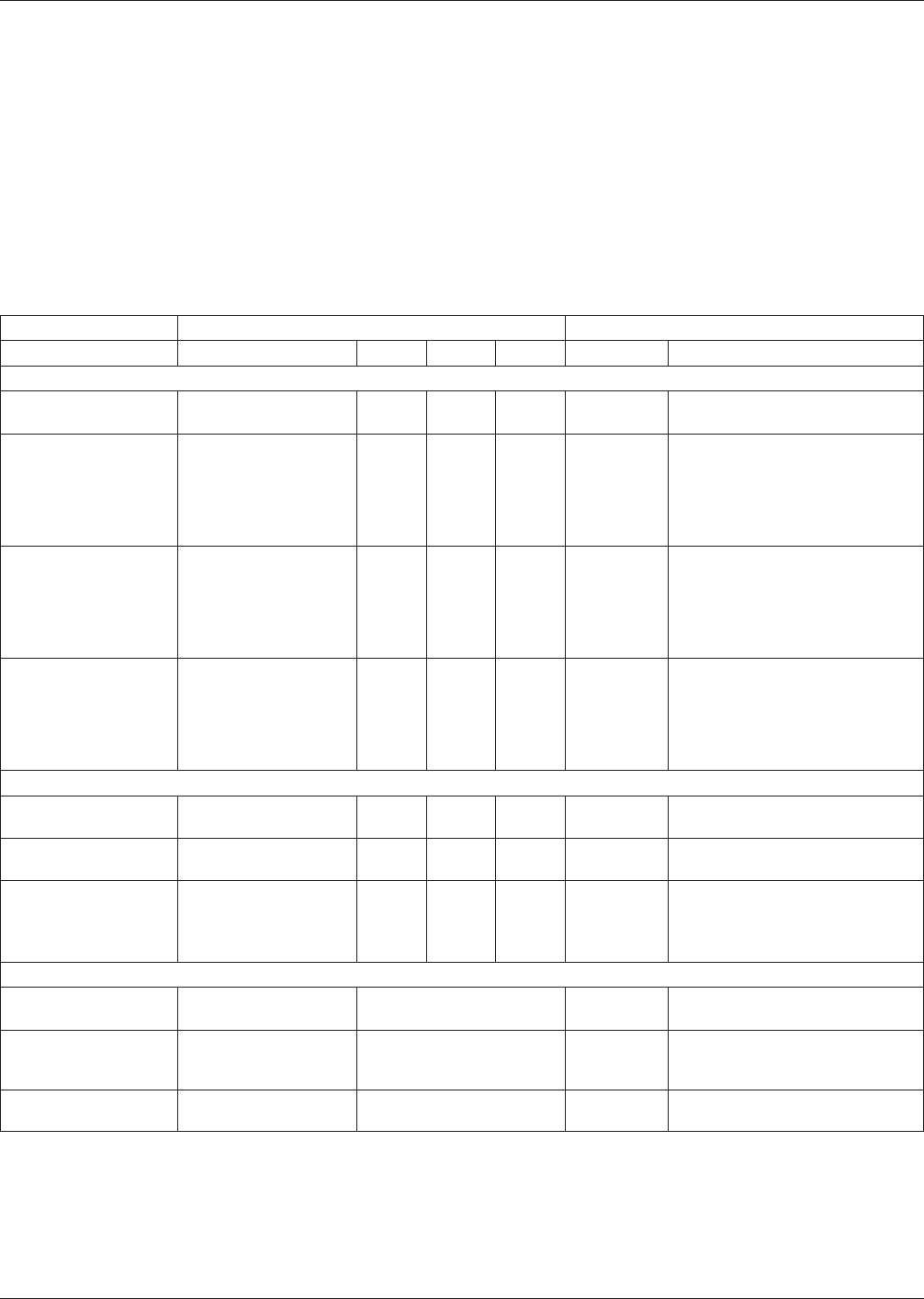
Table 3-1 Requirements of Electroless Nickel Electroless Palladium Immersion Gold (ENEPIG) Plating
Inspection Class/Test Frequency (A.Q.L.) Requirements
Tests Test Method 1 2 3/3A Paragraph Remarks
General:
Visual Visual 4.0 2.5 1.0 3.1
Uniform color and complete
coverage of surface to be coated.
Electroless Nickel
Thickness
Appendices 4 and 9 6.5 4.0 2.5 3.2.1
3 to 6 µm [118.1 to 236.2 µin] at
± 4 sigma (standard deviations)
from the mean as measured on
a nominal pad size of 1.5 mm x
1.5 mm [0.060 in x 0.060 in] or
equivalent area.
Electroless Palladium
Thickness
Appendices 4 and 9 6.5 4.0 2.5 3.2.2
0.05 to 0.30 µm [2 to 12 µin] at
± 4 sigma (standard deviations)
from the mean as measured on
a nominal pad size of 1.5 mm x
1.5 mm [0.060 in x 0.060 in] or
equivalent area.
Immersion Gold
Thickness
>0.030µm [1.2 µin] a
Appendices 4 and 9 6.5 4.0 2.5 3.2.3
t - 4 sigma
(standard deviations) below the
mean as measured on a nominal
pad size of 1.5 mm x 1.5 mm
[0.060 in x 0.060 in] or equivalent
area.
Physical:
Adhesion/Tape Test
IPC-TM-650,
Method 2.4.1
6.5 4.0 4.0 3.4
No evidence of plating and/or
solder mask removed.
Solderability J-STD-003 4.0 2.5 2.5 3.5
Refer to the applicable
performance specification.
Force Measurement -
When required, the
specified provisions
apply:
Force Measurement
Test
4.0 2.5 2.5 3.5.1
0.14 mN/mm minimum for
Eutectic SnPb testing.
0.19 mN/mm minimum for SAC
305 testing.
Environmental:
Cleanliness IPC- 5704
When tests required, AQL
shall be AABUS
3.6
Refer to applicable performance
specification.
SIR
IPC-TM-650,
Method 2.6.3.5;
GR78-Core
When tests required, AQL 3.6
shall be AABUS 3.6
1.0E+08 ohms
1.0E+10 ohms
Electrolytic Corrosion
IPC-TM-650,
Method 2.6.14.1
When tests required, AQL
shall be AABUS
3.7 AABUS
IPC-4556 January 2013
4
3.1 Visual ENEPIG surfaces shall be inspected in accor-
dance with the visual examination sections of the IPC-6010
series specifications, specifically IPC-6012 which specifies the
use of a nominal magnification of 1.75X (approx. 3 diopters).
The coverage shall be complete and the finish shall be uni-
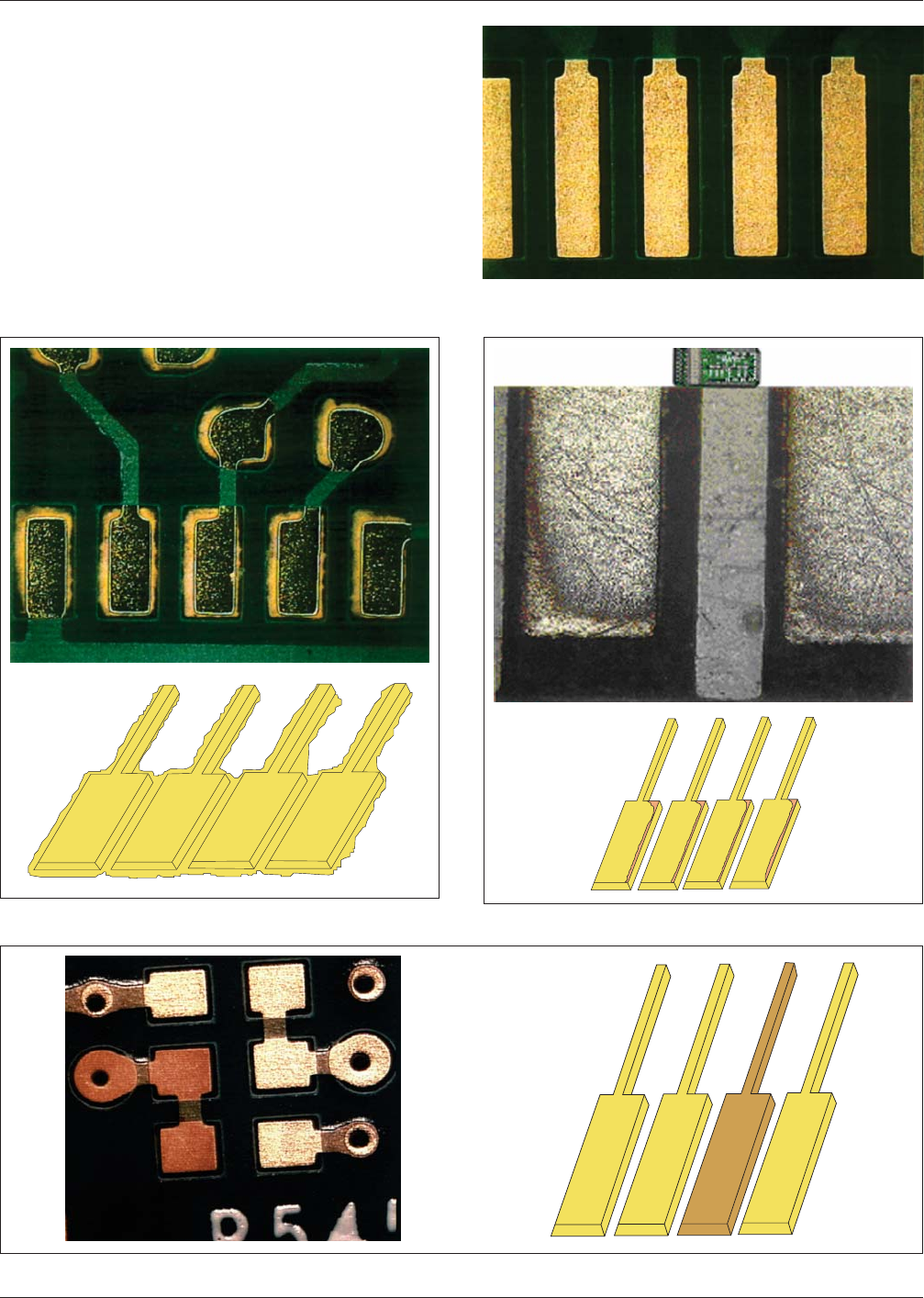
form on the surfaces to be plated (see Figure 3-1). For higher
magnification analysis, Figures 3-2 to 3-4 are offered for ref-
erence purposes. There shall be no extraneous plating or
nickel foot (see Figure 3-2), edge pull back (see Figure 3-3) or
skip plating (see Figures 3-4, 3-5 and 3-6) on the surfaces of
all classes of product.
Figure 3-1 Uniform Plating
IPC-4556-3-2a/2b
Figure 3-2 Extraneous Plating or Nickel Foot
IPC-4556-3-3a/3b
Figure 3-3 Edge Pull Back
IPC-4556-3-4a/4b
Figure 3-4 Skip Plating
January 2013 IPC-4556
5
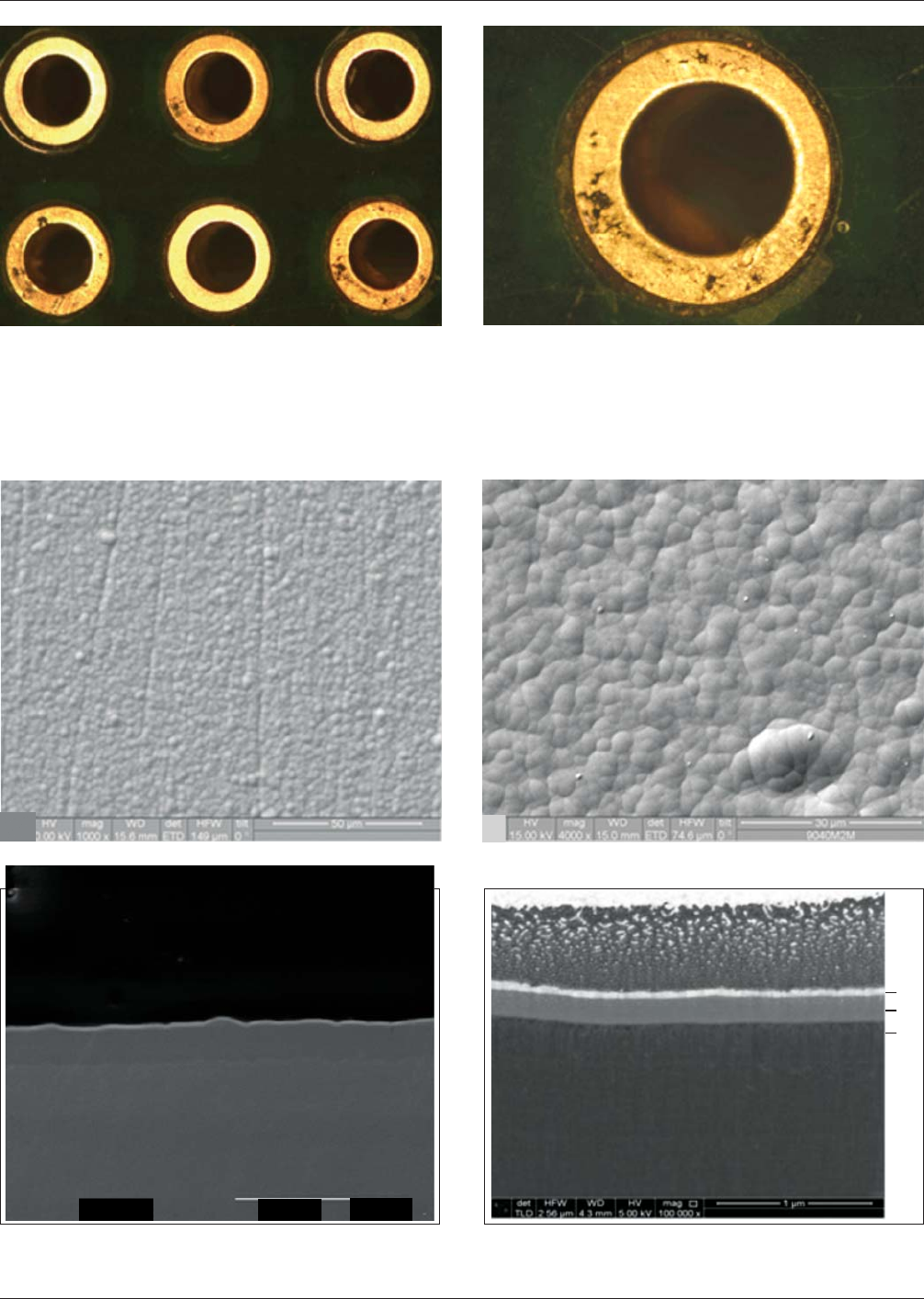
3.1.1 High Magnification Reference Images It may be necessary to evaluate the ENEPIG deposit using scanning electron
microscopy (SEM), transmission electron microscopy (TEM) or focused ion beam (FIB) as part of a qualification plan and
or for failure analysis. The images in Figures 3-7 through 3-12 in the following section are for reference purposes and were
provided by several different suppliers of ENEPIG.
Figure 3-5 Skip Plating of Gold Over Palladium Figure 3-6 Skip Plating of Gold Over a Palladium Deposit
Figure 3-7 1000X SEM Image of a Normal ENEPIG Surface Figure 3-8 4000X SEM Image of a Normal ENEPIG Surface
Figure 3-9 2500X FIB Image of a Normal ENEPIG Deposit Figure 3-10 100,000X FIB Image of a Normal ENEPIG
Deposit
Au
Pd
Ni
IPC-4556 January 2013
6
×2.5k
20kV
20 m
察
察