IPC-4556 印制板化学镍钯浸金(ENEPIG)规范ENG.pdf - 第25页
The Thickness of the ENEPIG to be Tested The thickness is the same as in the solderability test [see (1) above]. All com- binations were tested as follows: • Gold wire bonding utilizing ball, wedge or crescent. • All sam…

APPENDIX 2
Round Robin Test Summary
George Milad
Uyemura International Corporation
Objective To determine the appropriate specification limits for electroless palladium in ENEPIG for soldering and wire
bonding applications.
Supplier Participation Six suppliers namely: Atotech, Cookson Electronics, Dow Electronics Materials, MacDermid,
OMG and UIC Uyemura, committed to providing samples of the required finish for the Round Robin testing:
Thickness Measurement Industry capability to accurately measure the thickness of palladium in thickness ranges desired
to be applied to the test vehicle (TV) values was questioned by members of the sub-committee. Prior to the preparation of
the samples for the round robin testing of solderability and wire bonding performance, it was decided to obtain an ENEPIG
test sample to be sent to interested participants with measuring equipment to determine industry capabilities to reproducibly
measure thickness values. The test sample had 16 pads designated for measurement and recorded values were sent to Gerard
O’Brien for compilation. The results are provided in the specific Appendix 3, authored by Gerard O’Brien. Participants in
this study were able to use this data to confirm their own measurement capability and to identify any need for changes in
their measurement protocols.
Solderabilty and Solder Joint Reliability Testing
The Test Coupon The ‘‘W Coupon’’ described in the IPC-6012 document was used for this phase of the Round Robin. The
coupon is 16.5 cm X 14.0 cm [6.5 in X 5.5 in]. It has 18 sub-units as shown above, as well as 2 detachable BGA coupons.
All submitted samples will be subjected to the stress or conditioning for 8 hours at 72 °C [162 °F] and 85% RH.
Thickness of the ENEPIG to be Tested After additional discussions, the thicknesses of the multiple layers to be tested
were agreed upon and all suppliers targeted the desired thicknesses.
• Electroless Nickel (EN): 5 µm±1µm
• Electroless Palladium (EP): 0.1 µm, 0.2 µm, 0.3 µm and 0.5 µm*
*(from only one supplier).
• Immersion Gold (IG): Supplier preferred immersion gold process (one supplier chose to supply a second ENEPIG sample
set with a very thin immersion gold layer).
All combinations will be tested as follows:
• Soldering with eutectic solder
• Soldering with Lead Free SAC305 alloy
Sample Size Each supplier agreed to provide 6 ‘‘W Coupons’’ per thickness iteration. All samples were shipped to Gerard
O’Brien for coding, prior to being sent to the test locations, to ensure anonymity of the supplier. Gerard will also maintain
a record of the actual thickness plated on each set of coupons, based on measurements made at a single (referee) test
location.
Solderability/Wettability This was evaluated using ‘‘Wetting Balance’’ testing as well as Spread test coupons. Wetting
Balance tests were carried out by G. O’Brien of ST and S Group (see APPENDIX 5). Solder spread testing was conducted
by Brian Madsen of Continental Automotive Systems (see APPENDIX 6).
Solder Joint Reliability Ball Shear testing on the BGA portion of the coupon was used to make this assessment. The testing
was carried out at Rockwell Collins by David Hillman. Both force and fracture mode were recorded. Cross sections of rep-
resentative samples were prepared to examine the composition of the intermetallic compound (IMC) and its configuration.
The data is reported by David Hillman in APPENDIX 7.
Wire Bonding Evaluation
Wire Bonding Coupon The test coupon design was provide by Horst Clauberg of Kulick & Sofa. James Monarchio at TTM
manufactured the test coupons. Jim supplied sets of test coupons at 2 different levels of surface roughness. One to be par-
ticularly coarse (RA ~ 380), utilizing mechanical scrubbing. The surface roughness was measure by profilometrry at Enthone
by Karl Wengenroth.
IPC-4556 January 2013
14

The Thickness of the ENEPIG to be Tested The thickness is the same as in the solderability test [see (1) above]. All com-
binations were tested as follows:
• Gold wire bonding utilizing ball, wedge or crescent.
• All samples are pre-conditioned for 4 hours at 150 °C [302 °F], before bonding.
• The wire bonding testing was done by Stephen Meeks of St. Jude Medical. For the protocol and results of the wire bond-
ing evaluation, please refer to APPENDIX 8.
January 2013 IPC-4556
15
APPENDIX 3
ENEPIG PWB Surface Finish XRF Round Robin Testing
Gerard O’Brien, President
STandSGroup
INTRODUCTION
Measurement capability for thin immersion coatings has long been a concern for the 4-14 Subcommittee and with the intro-
duction of Electroless Nickel/Electroless Palladium/Immersion Gold (ENEPIG), this has become a bigger issue with the need
to measure three plated deposits. Additionally there is the impact of the phosphorus content in the Electroless Palladium that
was present in the majority of samples submitted for the generation of this specification. For previous 455X family specifi-
cations, the committee has typically verified the deposits submitted by the chemical suppliers using a reference XRF (X-ray
Fluorescence) and the delta between the readings shared with the suppliers and a general comparison chart generated. There
were a significant number of ENEPIG users and printed board (PB) suppliers, as well as chemical suppliers involved with
the generation of this specification, who expressed an interest in understanding the variability and accuracy issues with mea-
suring using XRF and so it was decided to perform a round robin test with all interested parties measuring a previously
‘‘certified’’ coupon.
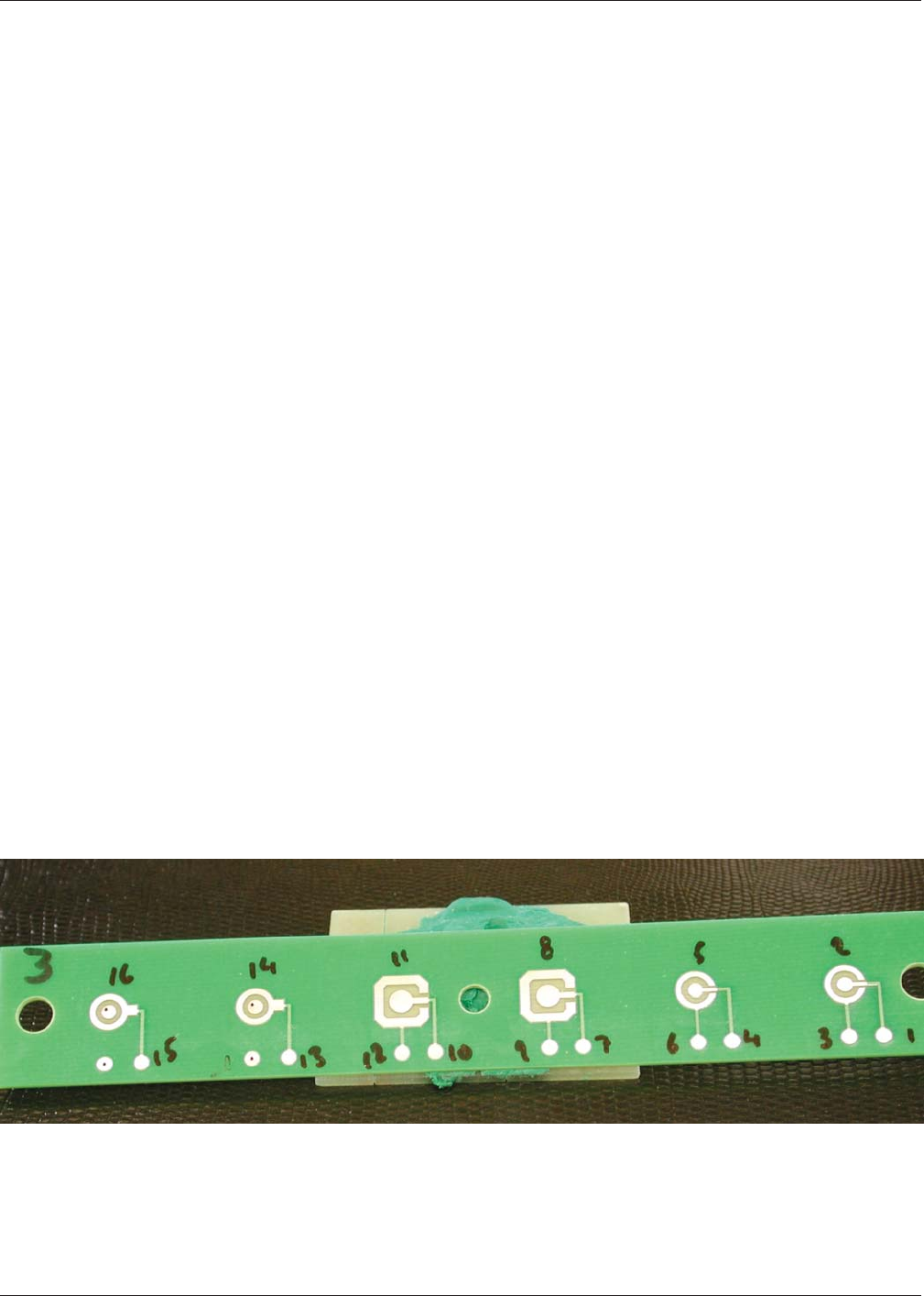
A previously plated test coupon for switch pad testing, but never tested, was chosen for this purpose at random and sixteen
locations on the coupon were identified for measuring. A letter detailing the protocol was supplied with the sample and sent
initially to the six chemical suppliers prior to plating their test submissions. The test vehicle was then forwarded around the
world to OEMs, CEMs and PB suppliers. The data was returned to S T and S and coded to protect the source of the data.
Feedback was provided to each test site as to where their readings were relative to the actual values for Ni, Pd and Au. Based
on the data generated, some test locations asked for another chance to read the coupon after their XRF had been adjusted
or repaired.
The XRF capability used for this round robin testing ranged from simple proportional counter systems all the way through
vacuum assisted focused capillary systems costing $200K+. It should be noted that the higher cost systems did not always
produce the correct answers and that a correctly set up XRF system of any type with sufficient measurement time can be
capable of correctly measuring the ENEPIG deposit.
It was discovered during this testing that the use of incorrect calibration standards is still a reality. Non-phosphorus contain-
ing nickel standards were a common occurrence as well as gold foil thicknesses outside the measurement range. It cannot
be emphasized enough that correct measurements can only be obtained when using ENEPIG standards with the phospho-
rus content in the nickel and palladium matching that in the plated deposit.
Figure A3-1 shows the test coupon and pertinent information from the protocol sent to the test locations. Figures A3-3, A3-4,
and A3-5 show the recorded test data for the Au, Pd, and Ni measurements, respectively. Level C shows the reference data.
Figure A3-1 Test Coupon Used for XRF Round Robin Measurements
IPC-4556 January 2013
16